A
VAC VOICE ALARM SYSTEM
A
VAC Installation and Maintenance Manual • Approved Document No. DAU0000402 Rev 6 • Page 23
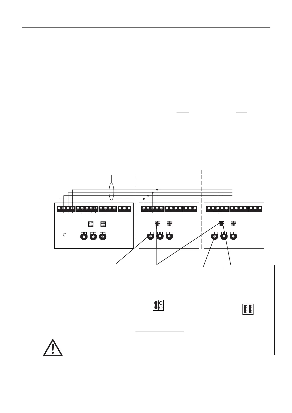
SLAVE AVAC CONNECTION
To increase audio coverage in large areas such as warehouses, shopping centres, etc, up to 10
slaves can be connected to one master.
For compliance with BS 5939-8, all critical life safety broadcasts made at the AVAC master (i.e.
emergency microphone announcements, Evacuate, Alert and Test messages) are automatically
passed to the relevant slave(s) for output.
To allow greater paging and background music flexibility, each slave has its own paging and
BGM inputs. Alternatively, for global paging and background music, the audio source(s) at
the master can be daisychained to the slave’s inputs as explained on pages 20 and 21.
Slaves connect to masters as shown below. Please note, to ensure slave AVACs are monitored
correctly, the right hand PLK2 link (
Master/Phantom) MUST only be fitted at the LAST slave
in the daisychain. The left hand PLK2 link (Local Fault) should be fitted at ALL slaves.
PTT
SIG 0V +V
Fire Mic Input
SIG
MASTER
AVAC
PTT
SIG 0V
Paging Input
SIG 0V
BGM Input
PTT
SIG 0V +V
Fire Mic Input
SLAVE
AVAC
PTT
SIG 0V
Paging Input
SIG 0V
PTT
SIG 0V +V
Fire Mic Input
PTT
SIG 0V
Paging Input
SIG 0V
BGM Input
BGM Input
}
T
o next slave
(
if fitted)
SLAVE
AVAC
0V
Go
Slave output
Local
Fault
FireMic
PLK2
Master/
Phantom
Page
PLK3
/10
Audio
Limit
FireMic
Page
BGM
Local
F
ault
FireMic
PLK2
Master/
Phantom
Page
PLK3
/10
FireMic
Page
B
GM
Local
Fault
FireMic
PLK2
Master/
Phantom
Page
PLK3
/10
FireMic
Page
B
GM
All emergency microphone
broadcasts (see page 19 for emer-
gency microphone connection
details) and digital message
broadcasts are routed to the
slave(s) via these four wires.
(Refer to pages 20 and 21 for information on how to
implement global and/or localised paging and BGM)
Typical slave AVAC connection
The right hand PLK2 link
(
Master/phantom) must
ONLY be fitted at the last
slave in the master-to-
slave daisychain to ensure
the chain is monitor
ed
correctly.
If only one slave is used,
the right hand PLK2 link
(Master/phantom) would
be fitted on that slave’s
Main PCB.
T
ur
n clockwise to
increase slave
AVAC volume
Turn clockwise
to incr
ease
slave AVAC
volume
The left hand PLK2 link
(Local Fault) must be
fitted at ALL slaves to
ensur
e any faults ar
e
signalled at the master
FireMic
PLK2
Local
Fault
Master/
Phantom
FireMic
PLK2
Local
Fault
Master/
Phantom
Note that the Fir
e Mic input on all slave A
VACs will show a fault
until the system has been calibrated as detailed on page 16.
www.acornfiresecurity.com
www.acornfiresecurity.com