A
VAC VOICE ALARM SYSTEM
A
VAC Installation and Maintenance Manual • Approved Document No. DAU000040 Rev 6 • Page 13
MAINS WIRING & CONNECTION DETAILS
T
he general requirement for the mains supply to AVAC’s power supply PCB is fixed wiring,
using three core cable (no less than 1mm
2
and no more than 2.5mm
2
) or a suitable three
c
onductor system, fed from an isolating switched fused spur, fused at 3A. This should be
secure from unauthorised operation and be marked ‘FIRE ALARM SYSTEM: DO NOT SWITCH
OFF’. The mains supply must be exclusive to the AVAC unit.
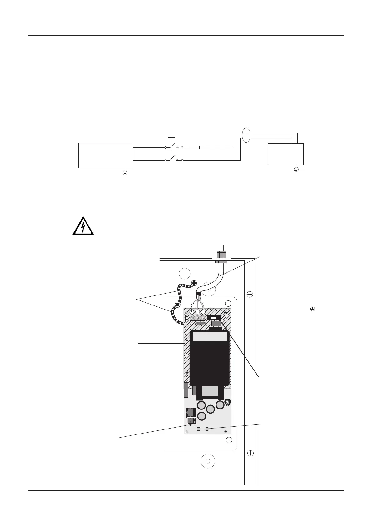
(As an alternative to a switched fused spur, a double pole isolating device may be used (see
diagram below) providing it meets the appropriate national wiring regulations).
DO NOT attempt to connect mains to the AVAC until you are fully conversant with the layout
and features of the power supply PCB, as described below.
The power supply PCB combines the functions of a mains to d.c. switched mode power supply
unit, battery charging unit and battery monitoring unit.
THE POWER SUPPLY PCB STORES VOLTAGES AT UP TO 400 Vd.c. AND MAY BE
LETHAL IF TOUCHED. DO NOT TOUCH THE PCB WHILST THE RED ‘HAZARDOUS
VOLTAGES PRESENT’ INDICATOR IS LIT.
≥ 3mm
≥
0.75mm
2
< 2.5mm
2
3A
MAIN
DISTRIBUTION
BOARD
A
VAC
PSU EARTH STRAPS
DO NOT operate AVAC without
its earth straps connected in
this exact configuration
(The PSU earth strap connects the
power supply PCB to the chassis earth
post which in turn is connected to the
base earth post).
HAZARDOUS VOLTAGES
PRESENT LIGHT
When lit red, hazardous voltages
ar
e present on the components in
the hatched ar
ea of the PCB and
this charge is only bled away
after the mains supply has been
r
emoved. When the red light
extinguishes, the char
ge has
leaked away to a safe level.
Incoming Mains cable must be
segregated from other cables
and should only enter the
enclosure through one of the
knock-outs on the right side of
the enclosure. Good quality
cable glands must be fitted.
The incoming mains earth
wire MUST be connected to the
terminal marked
and not to the chassis or
base ear
th post.
If connecting stranded
mains cable (max 2.5mm
2
)
we recommend the use of
bootlace ferrules.
PRIMARY
FUSE (F1)
20 x 5 mm 1 A HRC Ceramic to
IEC 127 (EN60127 Part 2).
Do not use any other type or size
of fuse in this position.
BATTERY FUSE (F2)
20 x 5 mm 5 A F to IEC 127
(EN60127 Part 2).
Do not use any other type or size
of fuse in this position.
BATTERY LEAD
CONNECTOR
(battery leads are supplied in the
AVAC’s accessory pack). See page 14
for batter
y position and connection
details.
N
L
The Power Supply PCB
1
mm
2
<
2.5mm
2
www.acornfiresecurity.com
www.acornfiresecurity.com