A
VAC VOICE ALARM SYSTEM
AVAC Installation and Maintenance Manual • Approved Document No. DAU0000402 Rev 6 • Page 10
MOUNTING AVAC
The enclosure can be surface or semi-flush mounted (see page 11). It comprises a hinged metal
lid and metal back box containing all of the system’s electronics. To protect the electronics
against damage during first fix installation, most of the PCBs are located on a removable chas-
sis plate, as shown below.
The enclosure must be sited internally in an area not subject to conditions likely to affect its
performance, e.g. damp, salt-air, water ingress, extremes of temperature, physical abuse, etc.
It should be positioned at a height where it is easily accessible and in a prominent position
within the building. Ideally, the indicators on the front of the enclosure should be at eye level.
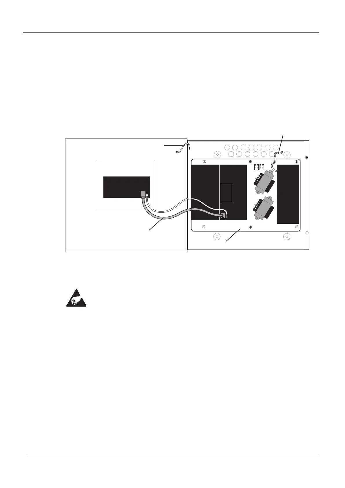
The AVAC Enclosure
Removing the lid and chassis plate
To expose all of the base mounting holes, the lid and chassis plate should be removed from
the enclosure prior to first fix installation.
Anti-static handling guidelines: Prior to handling any of the AVAC’s internal
components, operators should rid themselves of any personal electro-static charge by
momentarily touching any sound connection to safety earth, e.g. a radiator.
To remove the lid:
•
Undo the two scr
ews on the right hand side of the A
V
AC using the Allen key pr
ovided.
• Hinge the lid 180° to the left and remove the lid earth strap from the base earth connection
(take care not to overbend the hinges).
• Disconnect the lid/base connecting cables (PL6 and PL5) from the Main PCB. Take care to
depress the telecoms-style locking tab on the PL6 connector to prevent damage.
•
Car
efully r
emove the four wing nuts and washers that secure the hinges.
To remove the chassis plate:
• Ensure power has been removed from the AVAC and that the Power Supply PCB is safe to
handle (see page 13).
•
Pull the chassis ear
th strap of
f the spade connector on the base ear
th point.
• Remove all of the chassis plate’s retaining screws with the exception of the three keyhole
r
etaining scr
ews at the top of the chassis plate which should be loosened by about thr
ee turns.
• Push the chassis plate up and over the three keyhole retaining screws.
The lid and chassis plate can now be r
emoved from site to prevent accidental damage. They
should be stored in a clean, dry place which is free from vibration, dust and excessive heat.
P
OWER
SUPPLY
PCB
MAIN
PCB
AMPLIFIER
PCB
P
L6
DIGITAL
MESSAGE
STORE
PCB
CHASSIS EARTH STRAP
CHASSIS PLATE
INDICATOR
PCB
LID/BASE CONNECTING CABLES
LID EARTH STRAP
PL2
PL1
P
L5
www.acornfiresecurity.com
www.acornfiresecurity.com