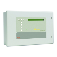
QT601-2 Quantec Controller
Installation & Programming Manual • Approved Document No. DNU6012001 Rev 5 • Page 11 of 42
2. Connect ‘spines’ and fix wiring to overdoor lights (call
points if overdoor lights are not used) and mark up the
Splitter Connection Record Sheet (located at the back of this
document).
3
. Wire ‘limbs’ in each individual room as required. Typical
room wiring diagrams are shown below:
Second Fix: 1st Stage
1. Fit the Quantec Controller.
2. Connect the network splitters and spines of the network.
3. Power up the system and check that all the network splitter
‘power‘ lights are on. If they are all off, there is probably a
short. If only one is off, there is an open circuit. Rectify any
faults. The integrity of the basic network is now proved.
4. Connect the rest of the equipment (call points, ceiling
pulls, overdoor lights, monitoring points, etc.) as detailed in
the wiring diagrams supplied with each device.
5. Plug the limbs onto the network splitters one at a time.
For each limb in turn check that the green power light on the
network splitter is lit and that the furthest networked point
on that limb goes into unassigned call when the device is
operated. Rectify any wiring faults as necessary.
Second Fix: 2nd Stage
Refer to Pre-Commissioning Instructions (Appendix 7) and
Programming Quantec section (Pages 15 to 29).
Device wiring when Overdoor Lights are used
(Loop the network through the slave overdoor lights then
wire spurs to the call points. This tends to reduce the
cable run to the furthest point.)
Device wiring when Overdoor Lights are not used
S
pine Length Calculator
Use the Spine Length Calculator (below) to work out the
maximum spine cable lengths taking into account the
number and type of devices connected to any network
splitter(s) on that spine. If several splitters are connected to
one spine then the calculation is for every
device connected
to that run of 1.5 mm
2
or 2.5 mm
2
cable on all splitters.
All spines wired from the Quantec Controller should be
calculated separately.
For the fictional nursing home highlighted earlier (Page 5),
which has two splitters connected to one ‘spine’, the points
calculation (with reference to the Spine Length Calculator)
would be as follows:
Displays (5 x 4 points) 20 points
Addressable OD Lights (3 x 7 points) 21 points
Call Points (23 x 1 point) 23 points
M
onitoring Points (5 x 1 point) 5 points
Slave OD Lights (21 x 1 point) 21 points
Ceiling Pulls (16 x 0 point) 0 points
Total Number of Device Points 90 points
Therefore, the maximum length of cable run for this
particular spine would be 300 metres of 1.5 mm
2
cable or 400
metres of 2.5 mm
2
cable.
Device Point Values
All Quantec devices have a ‘points’ rating which takes into
account their current consumption and voltage drop risk:
Call Point = 1 Addressable ODL / Sounder = 7
Monitoring Point = 1 Display = 4
IR Slave = 0.5 Display Interface = 1.5
Slave OD Light = 1 Ceiling Pull = 0
To determine the maximum length of a particular spine,
calculate the total points value of all the devices that will
be connected to any network splitter(s) on that spine and
read off the relevant figure on the graph above.
0
50
100
150
200
250
300
350
400
450
0100200300400500
1.5 sq.mm cable
TOTAL NUMBER OF DEVICE POINTS
2.5 sq.mm cable
LENGTH OF CABLE RUN (METRES)
SPINE LENGTH CALCULATOR

 Loading...