MOUNTING THE ENCLOSURE
The Quantec Controller is supplied with a plastic hinged lid, a
metal back box and three separate PCBs, the relative location
o
f which is indicated in Figure 1 below.
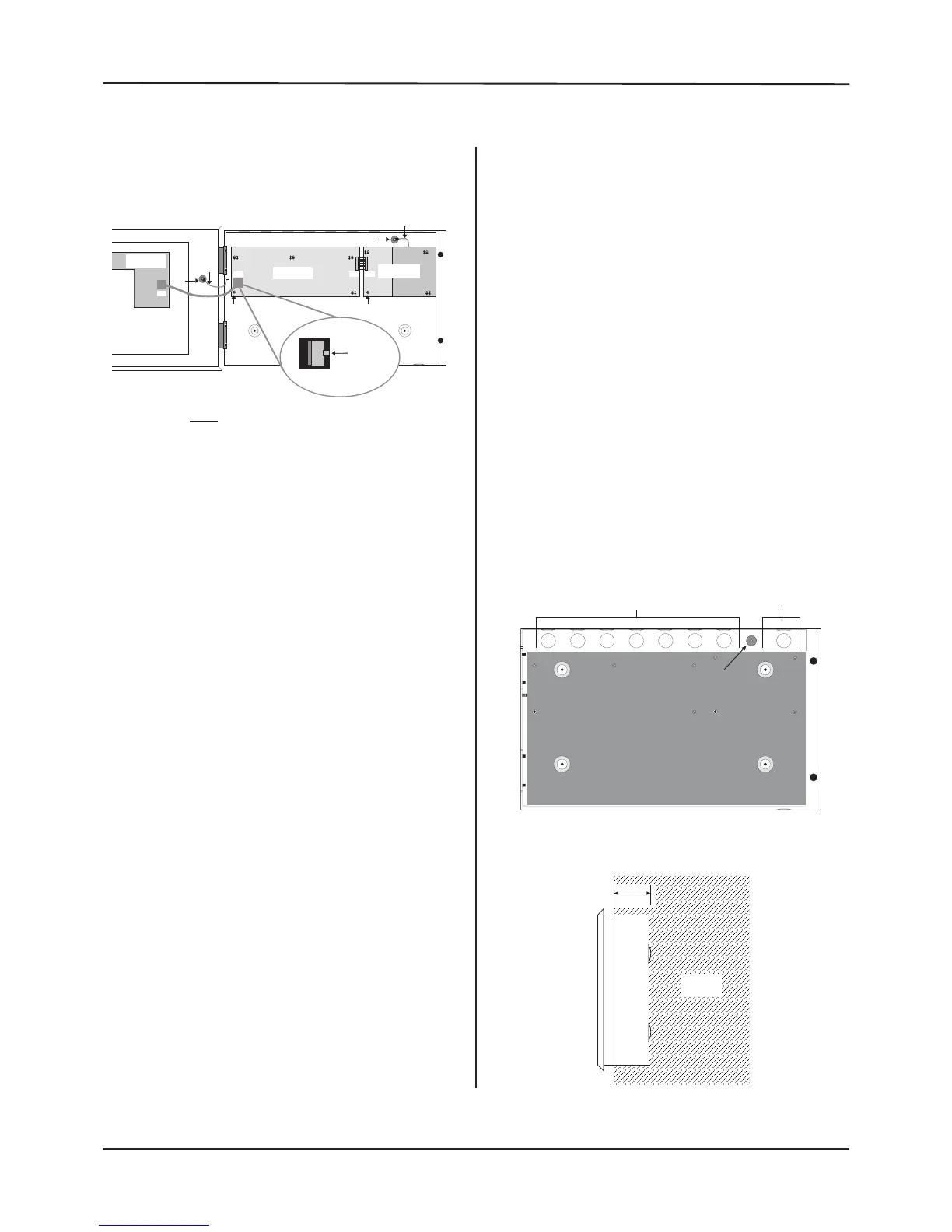
Figure 1 : Controller PCBs layout
The Controller must be sited internally in an area not subject
to conditions likely to affect its performance, e.g. damp, salt-
air, water ingress, extremes of temperature, physical abuse,
etc. The liquid crystal display on the enclosure's front should
ideally be situated at eye level.
The Quantec Controller can be surface, or semi-flush mounted
(refer to Figure 3, bottom right).
Exposing the Base Mounting Holes
To expose the Quantec Controller's base mounting holes, its
two base PCBs must first be removed. It is also recommended
that the hinged lid is removed to prevent accidental damage
during the fixing process.
To Remove the Lid:
• Take the Controller out of its box and undo the two screws
on the right hand side of the lid using the allen key provided.
• Hinge the lid 180° to the left (do not overbend the hinges).
• Disconnect the lid / base connecting cable (PL1) from the
Main Control PCB. Care should be taken when detaching this
connector to depress the telecoms-style locking tab to prevent
damage (refer to the inset in Figure 1 above).
• Carefully remove the four M4 retaining nuts that secure the
hinges.
To Remove the Base PCBs:
• Ensure power has been removed from the panel and that
the Power Supply PCB is safe to handle.
• Disconnect connector cable (PL5) on the Main Control PCB.
• Pull the PSU earth strap off the spade connector at the main
chassis earth point.
• Carefully undo the PCB retaining screw located at the
bottom left-hand side of the relevant PCB using a crosshead
screwdriver.
• Push the PCBs up and then forwards over the mounting
pillars taking care not to damage any of the components.
T
he Controller's lid and base PCBs can now be removed to
prevent accidental damage.
Note: The base PCBs are static-sensitive and relevant anti-
static handling precautions must be observed when handling
them. Refer to Appendix 3 for further details.
Decide carefully how the wiring will be fed into the panel
with reference to Figure 2 below and remove the required
k
nock-outs for cable entry. Always ensure that if a knock-out
is removed, the hole is filled with a good quality cable gland.
Any unused knock-outs must be securely blanked off.
It is essential that the 230 Va.c. cable is fed into the enclosure
via one of the inlets at the top right hand corner of the
enclosure. For further CRITICAL information on Mains
connection please refer to Page 13.
Using the four mounting holes, fix the base securely onto/into
the wall. The mounting holes are suitable for use with No.8
roundhead or countersunk woodscrews. Assess the condition
and construction of the wall and use a suitable screw fixings.
Any dust or swarf created during the fixing process must be
kept out of the enclosure and great care must be taken not
to damage any wiring or components.
Figure 2 : Internal view of back box (with PCBs removed)
showing mounting holes, knockouts and earthing points
QT601-2 Quantec Controller
Installation & Programming Manual • Approved Document No. DNU6012001 Rev 5 • Page 12 of 42