CONNECTING THE PANEL
The Power Supply PCB
THIS UNIT MUST BE EARTHED!
The Controller’s PSU combines the functions of a power supply
unit, battery charging unit and battery monitoring unit. It is
a
185-265 Va.c., 50-60 Hz off-line, switched mode PSU which
stores hazardous voltages of up to 400 Vd.c.
Mains Connection
DO NOT connect Mains to the PSU until the
installation is complete and all PCBs are correctly
attached, the lid/base connecting cable is in place, and
all retaining screws are firmly fastened down.
The general requirement for the Mains to the Controller is
f
ixed wiring, 3-core cable (no less than 0.75 mm
2
,
no more
than 2.5 mm
2
) or a suitable three conductor system that meets
the appropriate national wiring regulations.
The panel should be fed from an isolating switch fuse spur,
fused at 3 A. This should be secure from unauthorised
operation and be marked “CALL SYSTEM : DO NOT SWITCH
OFF”. This Mains must be exclusive to the Quantec Controller.
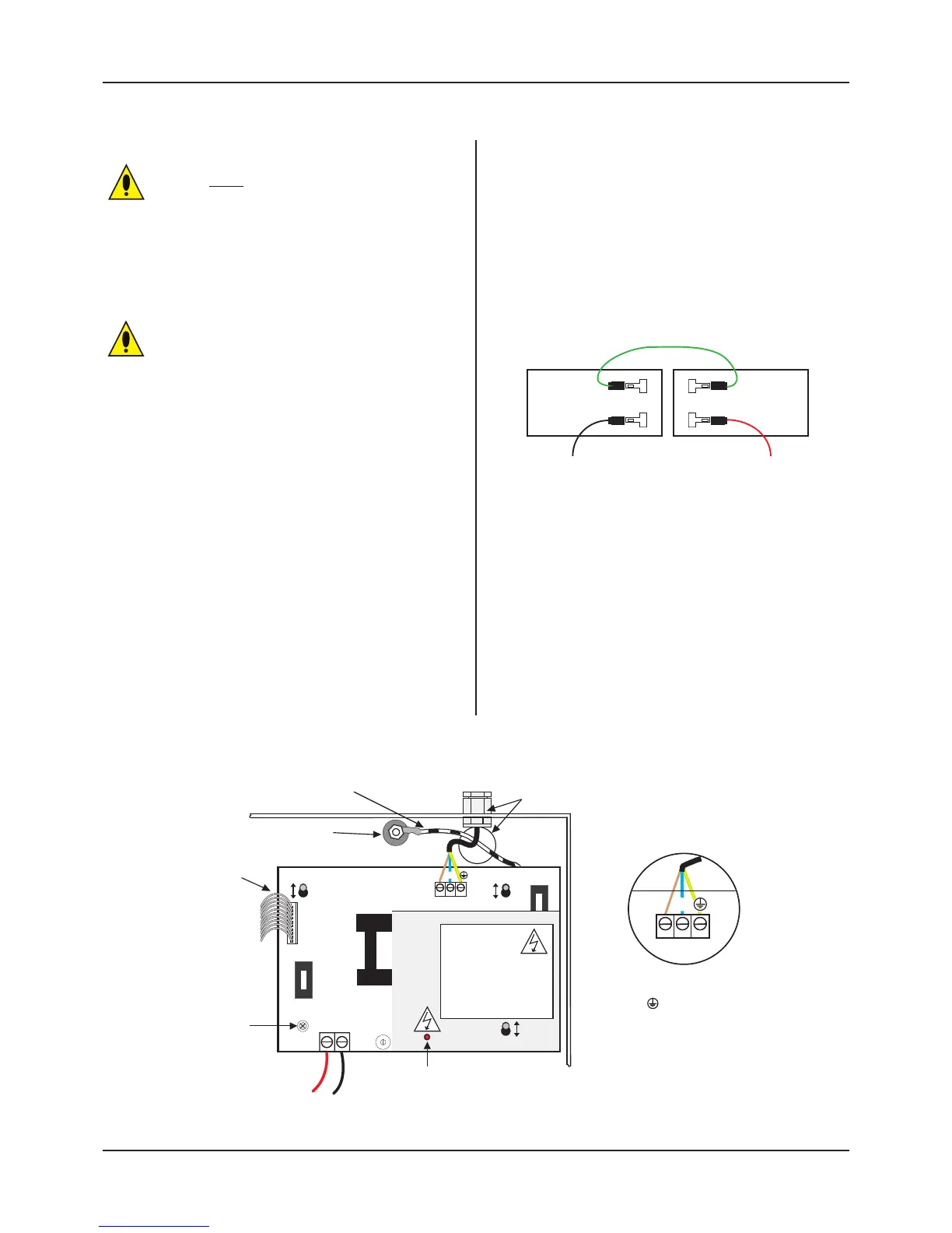
Correctly terminate the incoming cables, as shown in Figure 4
below. If required, the 5 mm connector block (CONN1) can be
pulled from the PCB for ease of installation. Ensure that the
incoming Mains earth is connected directly to this connector
block and NOT to the chassis earth point.
The Power Supply PCB is connected to the Main Control PCB
by a 10-way pitch connector. This connects from PL1 on the
Power Supply PCB to PL5 on the Main Control PCB.
Primary Fuse: 1 A HRC ceramic to IEC 127 (EN60127 Pt 2).
Battery Fuse: 3.15 A F to IEC 127 (EN60127 Pt 2).
DO NOT USE ANY OTHER TYPE/SIZE OF FUSE IN THESE POSITIONS.
Figure 4 : Mains Connection to Power Supply PCB
Standby Battery Connection
The power supply PCB contains circuitry that not only charges
stand-by batteries, but also measures the condition of them
to protect against deep discharge.
One feature of this circuitry is that it allows the installer to
power the system without connecting the mains supply. For
t
his to work, two fully charged 12 V VRLA batteries should be
connected in series, as shown below (always ensure correct
polarity connection).
IMPORTANT: When Quantec is powered up for the first time,
the Quantec Controller may need to reset its Configuration
Data to its default values. The message ‘Fit NVM Link’, or ‘E’
to Abort’ will be displayed. When the NVM link is fitted the
message ‘INITIALISING DATA, PLEASE WAIT’ will flash on the
display. This procedure may take up to 1 minute and MUST be
completed before Quantec will operate properly.
QT601-2 Quantec Controller
Installation & Programming Manual • Approved Document No. DNU6012001 Rev 5 • Page 13 of 42
CONN1
PRIMARY FUSE
1A 250V HRC
+
DO NOT
ADJUST
Chassis earth point.
DO NOT remove spade!
PSU earth strap
DO NOT operate the controller
without this strap!
Mains cable must be segregated from other
cables and should only enter the controller
through either of these two knock-outs.
Good quality cable glands must be fitted.
PCB retaining screw.
This must be secured
tightly before operation.
Note: Earth Faults do not
apply to this product.
Standby battery
connection
HAZARDOUS VOLTAGES PRESENT LED
When lit red, hazardous voltages will be present on the components in the
shaded area of the PCB. When power is removed, this charge is bled away.
Only when you have seen the red light extinguish can you be sure the charge
has leaked away to a safe level.
Protective cover.
This cover protects
against accidental contact
with circuit components
that may be charged
at up to 400 Vdc.
Note: Incoming Mains cable earth must
be connected to the terminal
marked and not the chassis earth point.
(The PSU earth strap connects the earth
to the chassis earth point.)
F2
Battery Fuse
3.15AF
F3
Charged Components
L
N
CONN1
N
L
PL1
BAT1
VR1
10-way pitch connector.
Connects to PL5 on
Main Control PCB.
-