QT601-2 Quantec Controller
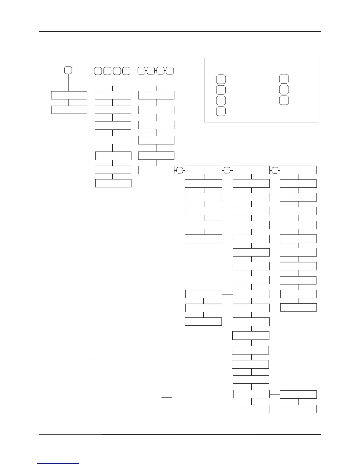
Overview of Access Levels
Installation & Programming Manual • Approved Document No. DNU6012001 Rev 5 • Page 16 of 42
Three ‘access levels’ are available at the Quantec Controller:
• General User (Access Level 1)
• Authorised User (Access Level 2)
• Engineer (Access Level 3).
All programming functions are located in Access Level 3 and
can be accessed by inputing a four digit code at the Controller
(default code = 3 3 3 3). Note: The Controller will automatically
exit Access Level 3 after 1 hour without a key press.
Entry to Access Level 2 requires the input of a different code
(default code = 2 2 2 2). Note: The Controller will automatically
exit Access Level 2 after 5 minutes without a key press.
Entry to Access Level 1 does not
require an access code.
The menu options available are shown on the menu tree
(right) and are described in detail in this section. Refer to the
subsection number below each menu option for detailed
information on that feature.
Note: The 'NVM' link (located on the Main Control PCB) must
be fitted during the programming process in Access Level 3.
This unlocks the non-volatile memory on the Controller and
allows site specific data to be modified.