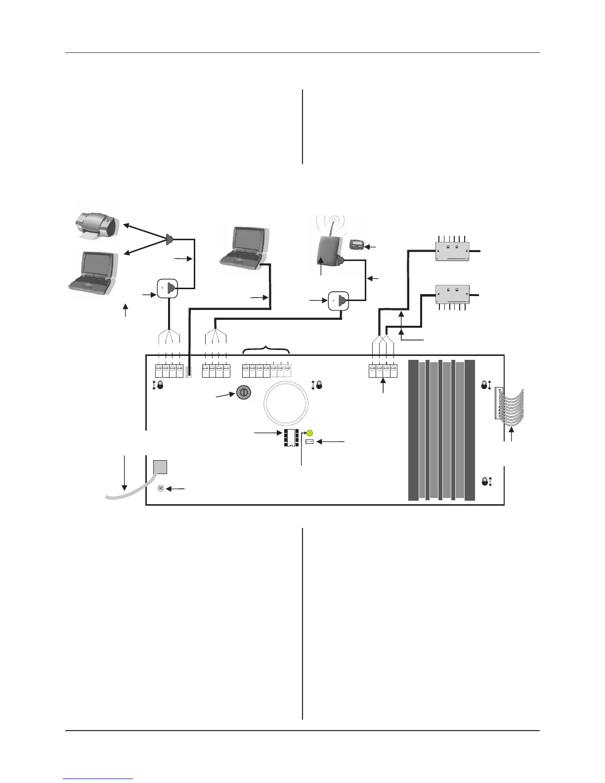
The Main Control PCB
The Main Control PCB includes all the terminals required for
the connection of the network wiring and optional system
ancillaries such as printer/PC/paging equipment. It also
features a 4-way pitch connector for the connection of an IBM
compatible PC for programming purposes.
Information on how to wire all of the above can be found in
Figure 5 below.
The Main Control PCB is connected to the Power Supply PCB
via a 10-way pitch connector (PL5) and to the Front Panel
Display and Switch PCB via an 8-way telecoms style cable (PL1).
QT601-2 Quantec Controller
+24V
P
L1
FRONT
P
ANEL
C
ONNECTOR
PL5
C
ONN2
PAGER
PLK1
L
INK TO
UNLOCK NVM
PSU
CONN5
N
ETWORK
CONN4
OUTPUTS
OP1 OP2 OP3 OP4 OP5 0V
CONN1
PRINTER/PC
N
VM
UNLOCKED
1C9
NVM
Blue
Black
Green
White
C
TS
0v Rx Tx
Blue
Black
Green
White
C
TS
0v Rx Tx
+
–
–
+
QT600S
(
wall socket)
P
rinter or QT707S Surveyor PC
connection
Q
T707 PC connection
for system programming
Auxiliary output
connections
s
ee bottom of page for details
(can be used for tone only paging)
A
lphanumeric radio
pager connection
N
e
t
wo
r
k
Sp
li
tt
e
r
Q
P
ower
Fault
N
e
t
wo
r
k
Sp
li
tt
e
r
Q
Power
Fault
Network connection
Refer to System Wiring Overview section
for detailed wiring information
Serial interface
l
ead (supplied with
Q
T707S software kit)
Connector lead
(
supplied with QT707
software kit)
BF874QAQ
(radio transmitter)
B
F877QAQ
(pager)
Serial
i
nterface
lead
QT600S
(
wall socket)
‘limb’ wiring
to ‘next’
splitter
to ‘next’
splitter
‘limb’ wiring
QT603 Network Splitters
Network ‘spine’ wiring
10-way pitch connector.
(connects to PL1 on
Power Supply PCB)
Two common network
connections are provided
for ease of wiring
Programming link
(when fitted,
allows site specific
programming data
to be edited)
NVM unlocked LED
(lit amber when
PLK1 programming
link fitted)
NVM
(non-volatile memory,
holds site specific data)
PCB retaining screw
(must be secured
tightly before operation)
Lid / Base connecting cable
(connects to PL1 on Front Panel
Display and Switch PCB)
V
R1 Volume Pot
(
turn to increase or
decrease buzzer volume)
P
L3
N
ote: For a multi-channel
Surveyor application, we
recommend using the AFP600S
isolatable wall socket.
Installation & Programming Manual • Approved Document No. DNU6012001 Rev 5 • Page 14 of 42
Printer/ PC Connection
CONN1 is provided for the connection of a standard 80
column RS232 printer (required if you wish to keep a
permanent record of data from the Controller's datalogger)
or a PC (required if you wish to utilise Quantec’s QT707S
Surveyor Data Management software).
The QT707S Surveyor software requires a PC running Windows
98, 2000, XP, VISTA or Windows 7 and is supplied with a CD,
QT600S (or AFP600S) wall socket and interface lead.
Most 80 column RS232 printers will work provided they are
set up as follows: data word = 8 bit; stop bit = 1; baud rate =
9600; parity = none. If in doubt, a pre-tested Printer Kit c/w
printer, wall socket and interface lead is available; Part No.
QT600P.
Laptop PC Connection (for programming)
If you wish to program Quantec using its QT707
upload/download software, an IBM compatible PC running
Windows 98, 2000, XP, VISTA or Windows 7 should be
connected to the PCB as shown. Quantec’s QT707 software kit
includes a lead with a 9-way serial port connector.
Radio Pager Connection
Alphanumeric radio paging can be achieved using a
BF874QAQ transmitter connected to the PCB via a QT600S wall
socket as shown above (the BF874QAQ kit includes the wall
socket and a serial interface lead). Alphanumeric display
pagers are also available separately (Part No. BF877QAQ).
Auxiliary Output Connection
A typical application for the Controller's auxiliary outputs is
to introduce tone only paging equipment onto the system, to
drive strobes or interface to other systems. Refer to Appendix
4 for typical wiring information.
Figure 5 : Main Control PCB Connection Details