QT601-2 Quantec Controller
Installation & Programming Manual • Approved Document No. DNU6012001 Rev 5 • Page 28 of 42
Appendix 3 - Anti-Static Handling Guidelines
Before handling PCBs, or any other static-sensitive components, please ensure that the following electro-static handling precautions
are taken.
Operators should rid themselves of any personal electro-static charge by momentarily touching any of the earth studs in the Quantec
Controller's metal back box with all circuit boards and connections correctly in place. This should be done immediately before
handling the sensitive components. If not in the vicinity of the back box, any other sound connection to safety earth may be
touched. Static sensitive items may now be handled with care.
Important: DO NOT touch the legs of any component and always handle PCBs by their sides.
PCBs should be stored in a clean, dry place which is free from vibration, dust and excessive heat. Retaining the PCBs in a suitable
cardboard box will also guard them against mechanical damage.
Appendix 4 - Auxiliary Outputs
Seven auxiliary outputs are provided at the Quantec Controller, as listed below:
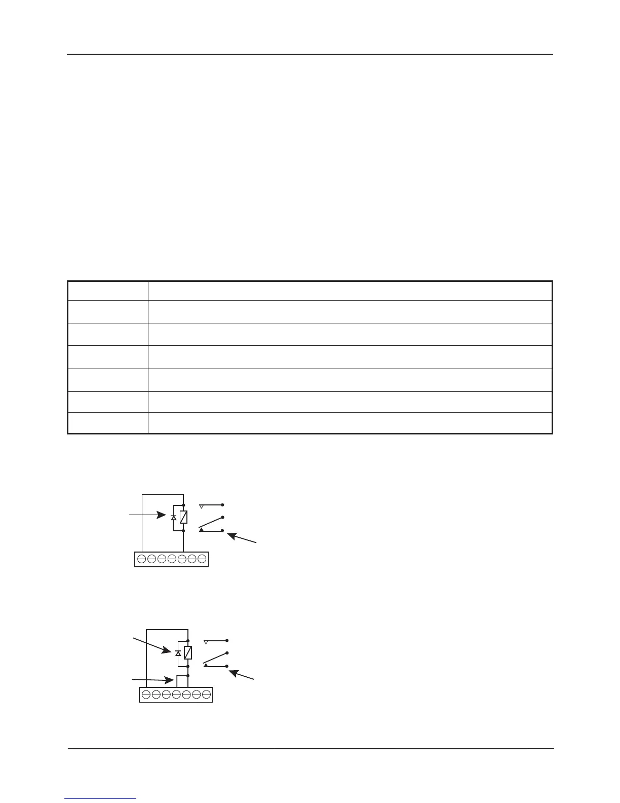
The outputs can be used for driving peripheral equipment, as per the following examples:
Example 1 : Activating a relay when an ATTACK call is present on the system.
Example 2 : Activating a relay when an ATTACK or EMERGENCY call is present on the system.
+24V +24 V (protected by 100 mA resettable fuse)
OP1 Activated when any STANDARD call is active on the system. Maximum current = 25 mA
OP2 Activated when any HELP REQUIRED call is active on the system. Maximum current = 25 mA
OP3 Activated when any EMERGENCY call is active on the system. Maximum current = 25 mA
OP4 Activated when any ATTACK call is active on the system. Maximum current = 25 mA
OP5 Fault Output. Normal = ON, Fault = OFF. Maximum current = 25 mA
0V 0 V