REMOTE IR INPUT
{{
– + R G
L+
SW
(all variants)
G Green light
R Red Light
– Network -Ve
– Network -Ve
+ Network +Ve
+ Network +Ve
RESET
ID
+V
S
R
Local
Switch
Red
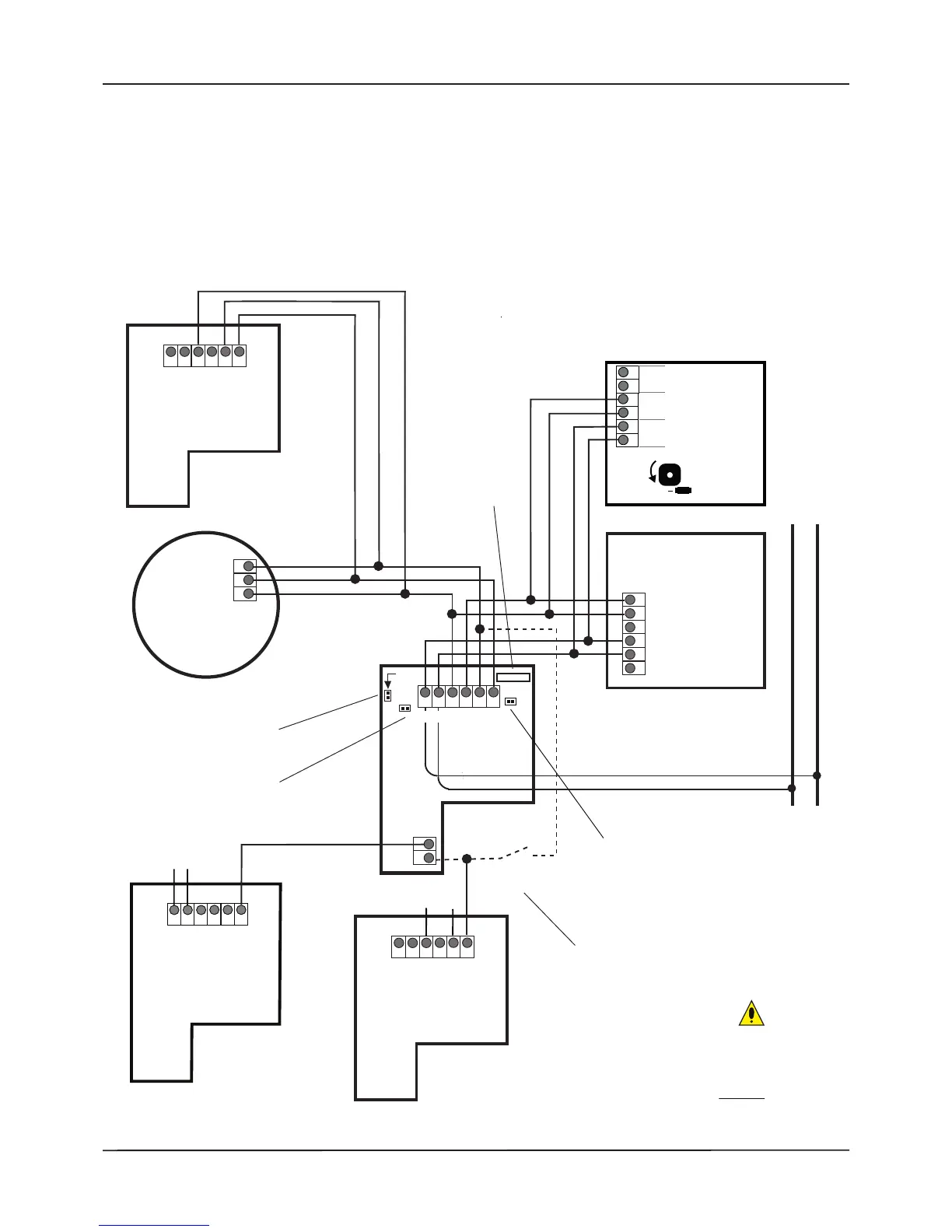
CONNECTION TO QUANTEC NETWORK
VIA ADDRESSABLE CALL POINT
IR
SLV
QUANTEC NETWORK
V
+
V–
S
MOM
S
ER
IR
{
Do not use
SLAVE IR RECEIVER
QT302RXS
– + R G
L
+
S
W
– + R G
L+
SW
LL
AC
3K
LP
{
SET ID PINS (PLK3 on QT302RX only)
{{
4
KLP
R
L+
SLAVE CALL INPUT
RESET PINS (PLK4 on QT302RX only)
For resetting diagnostic calls only.
L+
–
+
–
MASTER
CALL POINT
Slave Call
Input
ID RESET PINS (PLK2)
Short to clear the device’s ID
number when powered.
Short to give the QT302RX an ID when in
assignment mode (once assigned, these
pins can be used to make diagnostic calls).
For the optional connection of
third-party switches and buttons.
Max. 3 slave IR receivers
(connected in parallel)
per master ceiling
receiver/call point.
Max. 3 slave call points or ceiling pulls
(any mix, connected in parallel)
per master call point.
QT423 CONFIG
CONNECTOR
(PLK1)
For optional special
programming
functions (requires
QT423A adaptor).
+
–
QT607
CEILING PULL
(OPTIONAL)
Max. 3 slave call points or
ceiling pulls (any mix,
connected in parallel)
per master call point.
(on master)
(on master)
The TOTAL number of slave
devices with confidence
LEDs across all of an
addressable call point's
inputs must not exceed 3.
K2LP
– + R G
NET
REM
ODL
DISINT
VOLUME
HL EB
REM
BEEP
QT602D
SLAVE CALL POINT
(OPTIONAL)
QT602D SLAVE
CALL POINT
(OPTIONAL)
{
{
{
{
QT606S SLAVE
O
VERDOOR
LIGHT
C/W SOUNDER
(OPTIONAL)
QT606 SLAVE
OVERDOOR LIGHT
(OPTIONAL)
Installation & Programming Manual • Approved Document No. DNU6012001 Rev 5 • Page 31 of 42
QT601-2 Quantec Controller
Important Note Regarding IR Devices:
Due to the high risk environments in which infrared devices are likely to be used, be sure to install them so the best possible
reception is achieved. If in doubt, contact your supplier/the technical dept. for advice.