12 Serviceanleitung / Service Manual / / /
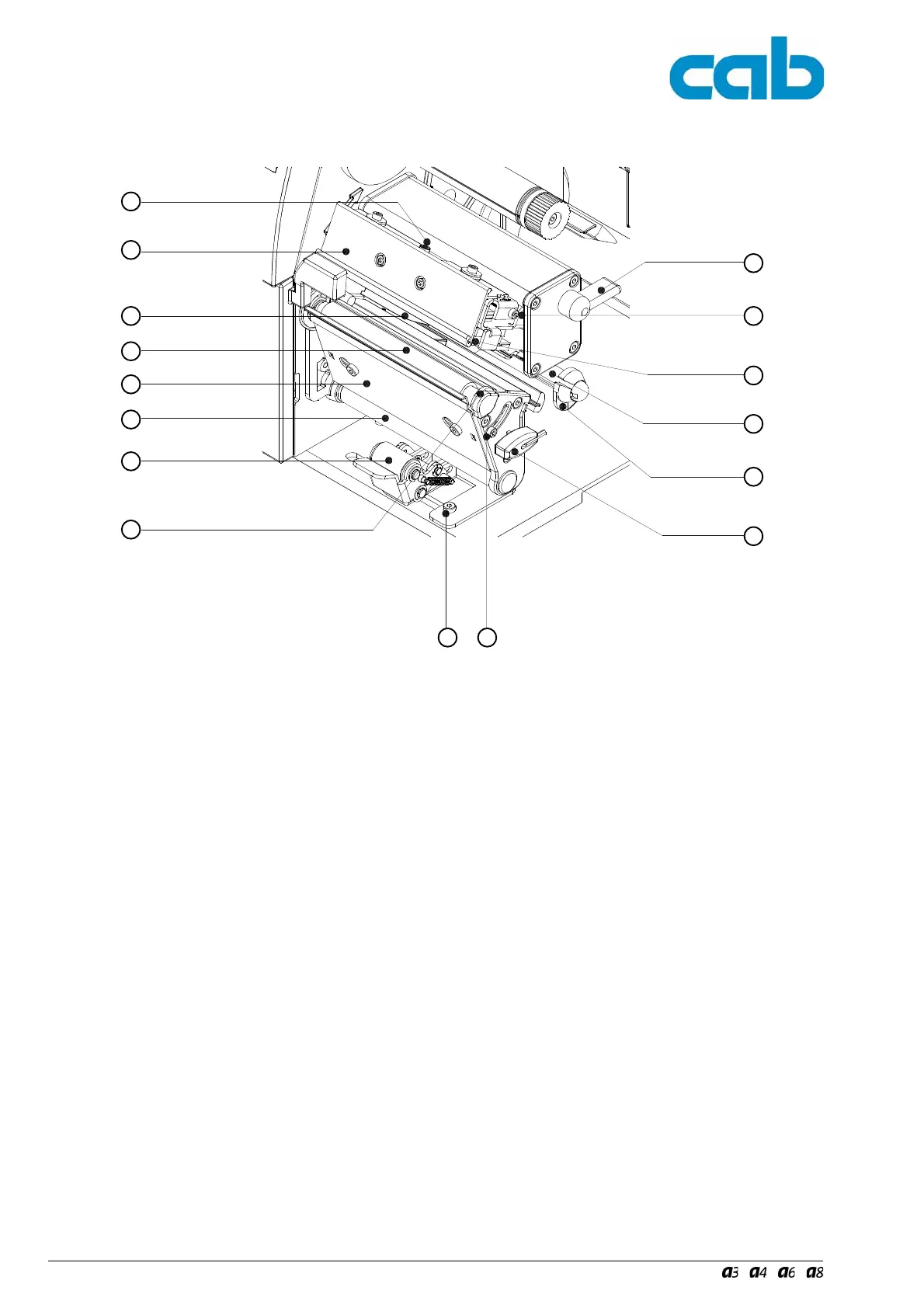
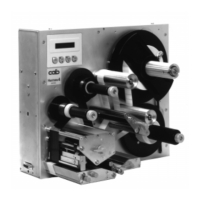
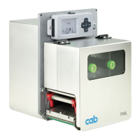
Bild 2 Druckmechanik
1 - Schraube zur Druckkopfbefestigung
2 - Transferfolienumlenkblech
3 - Etikettenlichtschranke
4 - Druckwalze
5 - Spendekante (nur bei A-Serie P-Version)
6 - Umlenkwalze (nur bei A-Serie P-Version)
7 - Andrucksystem (nur bei A-Serie P-Version)
8 - Druckkopfabstützung
9 - Feststellschraube zur Einstellung des Andruck-
systems (nur bei A-Serie P-Version)
10 - Feststellschraube zur Einstellung der Druckkopfab-
stützung
11 - Sechskantschlüssel
12 - Führungsring
13 - Umlenkachse (A3)
Schwinge (A4, A6 und A8)
14 - Thermodruckkopf
15 - Schraube zur Justage des Transferfolienumlenk-
blechs
16 - Hebel zur Druckkopfverriegelung
Fig. 2 Print Mechanism
1 - Printhead locking screw
2 - Ribbon shield
3 - Label edge sensor
4 - Media feed roller
5-Dispense plate (for A-Series P-version only)
6-Rewind assist roller (for A-Series P-version only)
7-Locking system (for A-Series P-version only)
8 - Printhead support
9-Screw for adjusting locking system (for A-Series P-
version only)
10 - Screw for adjusting printhead support
11 - Allen key
12 - Media guide
13 - Guide axle (A3)
Swing (A4, A6 and A8)
14 - Thermal printhead
15 - Screw to adjust the ribbon shield
16 - Printhead lever
1
2
3
4
5
8
10
11
12
13
14
15
16
6
7
9