2-8 J-Type CCM
J-Type Revision J2005-2
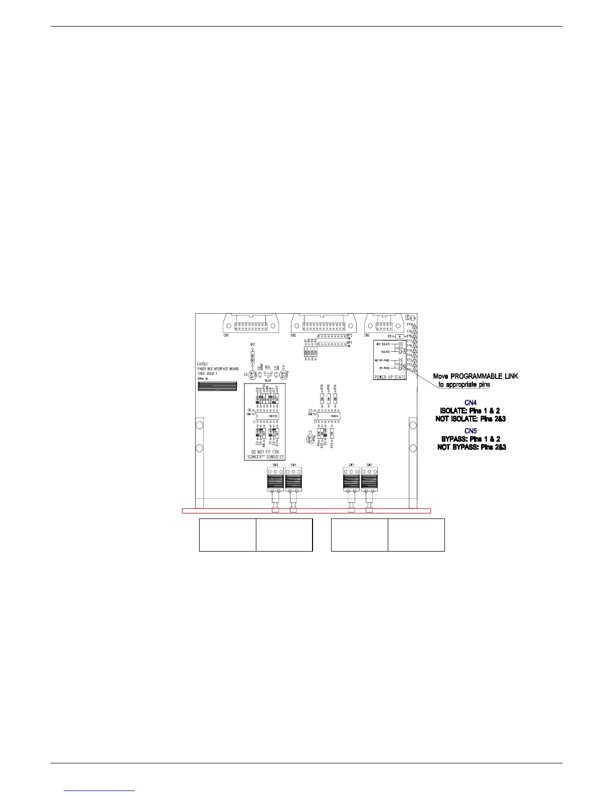
The factory setting is NOT ISOLATE, so that the
programmable jumper
is set to link
pins 2 and 3.
To change the POWER-UP STATE to ISOLATE:
Pull off the
programmable jumper
and replace it so that pins 1 and 2 are linked.
517 )DGHU#LQWHUIDF H#PRGXOH#+:636,
The Fader Interface module is fitted in the fader well below the CCM module and pro-
vides the connections between the faders and CCM.
Note: If the CCM is moved, the 7303 module MUST be moved with it. The 7303
MUST be connected to the 20-way ribbon coming from the CCM position otherwise,
fader communications will not work.
The front panel of the module contains the global “All Fader” BYPASS and ISOLATE
switches (see figure fig 2-5).
51714 $OO#) DGHU#%\SDVV
When the SET switch is pressed, all faders in the console are put in BYPASS mode.
When the CLEAR switch is pressed, all faders in the console are put in normal VCA
mode.
The switches are recessed slightly to avoid accidental operation.
$OO#)DGHU
%\3DVV
6HW####&OHDU 6HW###&O HDU
$OO#)DGHU
,VROD WH
FIG 2-5. J-type mkIII fader power start up option selection.‘