J-Type CCM 2-7
Revision J2005-2 J-Type
516 ,QWHUQDO#PRGXOH#VHWWLQ JV
51614 6HOHFWLRQ#RI#&38#F ORFN#VSHHG
The selection of the clock speed for the CCM module determines which type of com-
munications is to be used. The CPU clock speed jumpers are found on the
7249 J-
Type CCM MkII and 7835 J-type CCM MKIII Main Processor Board
.
Communications system CPU Clock Links required
Fast Copper 16MHz J3 to J4
RS 232 11.0592MHz J1 to J2, J4 to J5
To change the CPU clock speed, remove the CCM and place the module on a flat
surface with the front panel towards you. The 7249 or 7835 main processor board is
the large sub-board on the right or bottom of the module. Jumpers J1 to J5 are
located below U1 (the 80C152JA-processor chip). Use the links provided to set the
clock speed.
To use motor faders or SAM/Séance, Fast Copper is required.
51615 0RGXOH#SRZHU0XS#VWDWH#+,VR21LVR#VHOHFWLRQ,
When the console is first powered up, programmable modules may be set to power
up in ISOLATE mode or in NOT ISOLATE mode. This option is user selectable by
setting links on the motherboard. The factory setting is NOT ISOLATE.
6HOHFWLQJ#RU#FKDQJLQJ#WKH#RSWLRQV
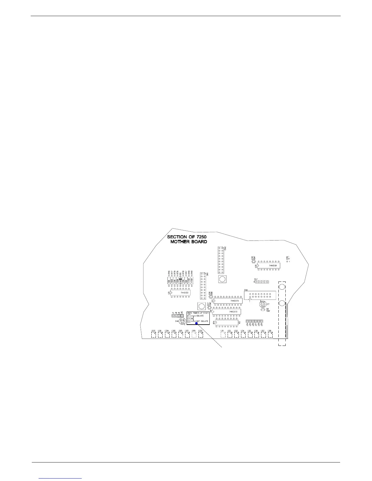
Place the CCM module on a flat surface so that the front panel is facing you and the
mother board is laying on the surface. Locate the three way male molex connector
CN26
. This can be found on the mother board near the EVENT LEDs
LD12
and
LD16
, close to the front panel.
CN26
is surrounded by a white rectangle and is
clearly labelled “POWER-UP STATE” (see fig 2-4 for details).
FIG 2-4. J-type mkIII CCM Power up state option selection.
Move PROGRAMMABLE LINK
to appropriate pins.
ISOLATE: Pins 1 & 2
127#,62/$7(=#3LQV#5#)#6