64
12345678901234567890123456789012123456789012345678
1
234567890123456789012345678901212345678901234567
234567890123456789012345678901212345678901234567
234567890123456789012345678901212345678901234567
234567890123456789012345678901212345678901234567
234567890123456789012345678901212345678901234567
234567890123456789012345678901212345678901234567
8
12345678901234567890123456789012123456789012345678
12345678901234567890123456789012123456789012345678
1
234567890123456789012345678901212345678901234567
234567890123456789012345678901212345678901234567
234567890123456789012345678901212345678901234567
234567890123456789012345678901212345678901234567
234567890123456789012345678901212345678901234567
234567890123456789012345678901212345678901234567
8
12345678901234567890123456789012123456789012345678
PRO FARMER TRIPLEXPRO FARMER TRIPLEX
PRO FARMER TRIPLEXPRO FARMER TRIPLEX
PRO FARMER TRIPLEX
PRO FARMER / TS • GENIUSPRO FARMER / TS • GENIUS
PRO FARMER / TS • GENIUSPRO FARMER / TS • GENIUS
PRO FARMER / TS • GENIUS
STANDARD FOXSTANDARD FOX
STANDARD FOXSTANDARD FOX
STANDARD FOX
USO E MANUTENZIONE USO E MANUTENZIONE
USO E MANUTENZIONE USO E MANUTENZIONE
USO E MANUTENZIONE
OPERATING AND SERVICEOPERATING AND SERVICE
OPERATING AND SERVICEOPERATING AND SERVICE
OPERATING AND SERVICE
Rev. 02
Fig. 41
A B C 1 2 3 4 5 6
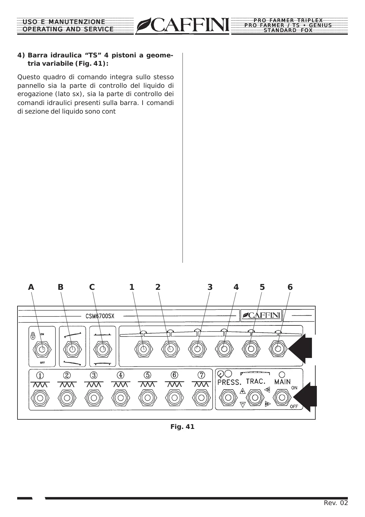
4) Barra idraulica “TS” 4 pistoni a geome-
tria variabile (Fig. 41):
Questo quadro di comando integra sullo stesso
pannello sia la parte di controllo del liquido di
erogazione (lato sx), sia la parte di controllo dei
comandi idraulici presenti sulla barra. I comandi
di sezione del liquido sono contrassegnati dal n°1
al n°7 ed aprono in sequenza da sinistra verso
destra tutte le 7 sezioni de barre corrispondenti.
Sotto i comandi di sezione troviamo il pulsante
“Press” che regola la pressione di erogazione
del liquido; premendo verso la posizione (+) au-
menteremo la pressione, premendo verso la po-
sizione (-) diminuirà. Il pulsante “Main” attiva o
disattiva la pressione dall’impianto, con il tasto in
posizione “ON” l’impianto verrà messo in pres-
sione e si apriranno tutte le sezioni di barra aper-
te (con il tasto ON), con il tasto in posizione
“OFF”, la pressione scenderà a “0” bar e verran-
no chiuse automaticamente tutte le sezioni de barre
aperte. I comandi idraulici posti sul lato destro della
console consentono di manovrare la barra dal posto
di guida.
4) “TS” hydraulic 4-piston boom (Fig. 41):
This control panel integrates on the same panel
both the liquid delivery control part (left side),
and the control part of the hydraulic controls
present on the bar. The liquid section controls
are marked by no.1 to no.7 and open in sequence
from left to right all 7 sections of corresponding
bars.
Below the section controls is the “Press”
pushbutton which regulates delivery of the liquid;
press towards position (+) to increase the
pressure, press towards the position (-) to redu-
ce the pressure. The “Main” pushbutton activates
or deactivates the pressure by the system, with
the key in the “ON” position, the system will be
pressurized and all open sections of the bar will
be opened (with the ON key), with the key in the
“OFF” position, the pressure will fall to “0” bar
and all the open bar sections will be closed.
The hydraulic controls located on the left side of
the console allow the bar to be manoeuvred from
the driver’s position.
COMANDI
SEZIONI
SECTION
CONTROLS
COMANDI
IDRAULICI
HYDRAULIC
CONTROLS