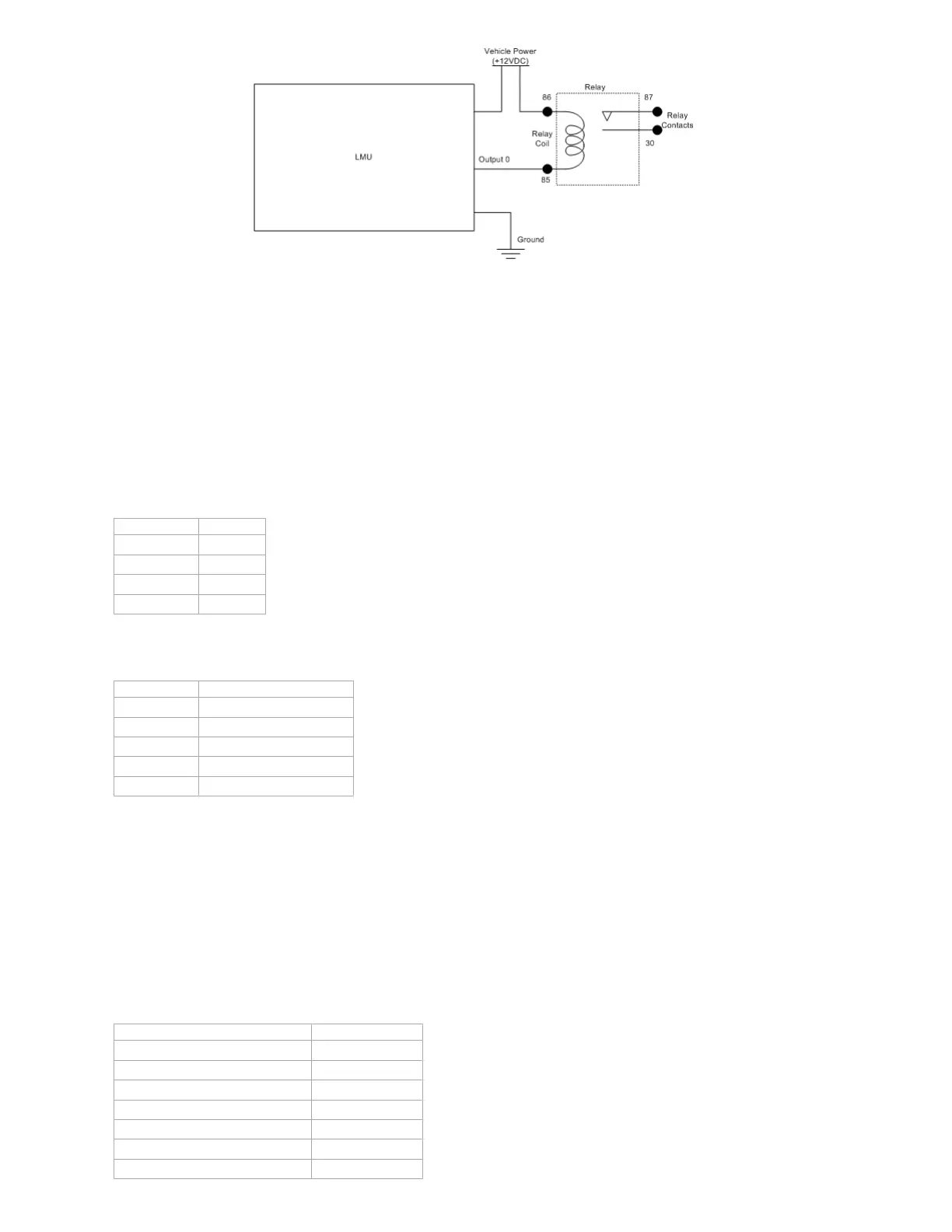
Sample Relay Wiring
4.7.3 LED Outputs
The LMUs 2 LED outputs are designed specifically to control external LEDs. The LED outputs have two states. When on, they provide 3.3V to the external
connector through a 100ohm series resistor. When off, these outputs are high impedance
4.7.4 Status LEDs
The LMU-5541™ is equipped with five Status LEDs; Power, BT, WiFi, GPS, COMM (wireless network). The LEDs use the following blink patterns to indicate
service:
LED #1 (Power LED - Red/Green) Definitions
Condition LED 1
LMU Off Off
U-Boot Red Solid
Kernel Start Green Solid
LMU On Red Solid
LED #2 (BT LED - Red/Green) Definitions
Condition LED 2
U-Boot Red Solid
Kernel Start Green Solid
BT Off No LED indication by default
BT On No LED indication by default
BT Connected No LED indication by default
Customer can define their own BT LED pattern by :
for Bluetooth LED Green :
echo 1 > /sys/class/gpio/gpio184/value
for Bluetooth LED Red:
echo 1 > /sys/class/gpio/gpio185/value
PEG action 133 is currently not supported on 5541 Platform
LED #3 (WiFi LED - Red/Green) Definitions
Condition LED 3
U-Boot Red Solid
Kernel Start Green Solid
WiFi Off Off
Client - Not Connected Searching Green Slow Flashing
Client - Not Connected Authenticating Green fast Flashing
Client - Connected Green Solid
AP Mode Red Solid
 Loading...