4.2 I/O Connector
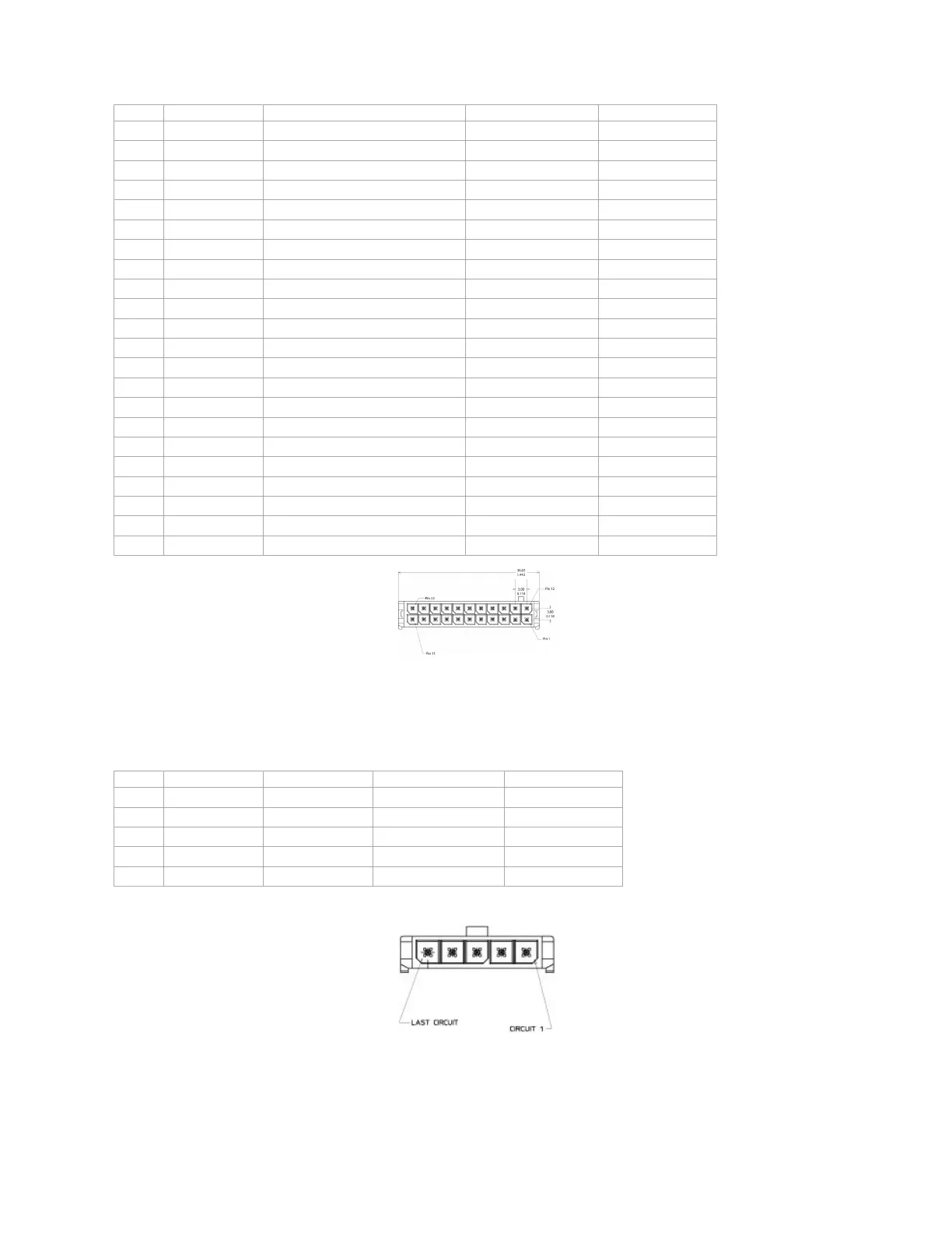
The LMU-5541™’s features expanded I/O capabilities via its 22-Pin Molex 43045-2202 connector. Its pin-out is as follows:
Pin Signal Name Description 5C889 Color Input or Output
1 Input 1 Input 1 – Digital Input Blue Input
2 Input 2 Input 2 – Digital Input Orange Input
3 Input 3 Input 3 – Digital Input Violet Input
4 Input 4 Input 4 – Digital Input Gray Input
5 Input 5 Input 5 – Digital Input Green & White Input
6 Input 6 Input 6 – Digital Input Blue & White Input
7 Input 7 Input 7 – Digital Input Black & White Input
8 1BB T Data 1 Bit Bus Data (T) Green & Black Input/Output
9 1BB GND 1 Bit Bus Ground Black Ground
10 1 BB R Data 1 Bit Bus Data (R) Orange & Black Input/Output
11 1 BB Gnd 1 Bit Bus Ground Black Output
12 Output 0 Output 0 - Starter Disable Relay Driver Green Output
13 Output 1 Output 1 - Digital Output Brown Output
14 Output 2 Output 2 - Digital Output Yellow Output
15 Output 3 Output 3 - Digital Output Blue & Orange Output
16 Output 4 Output 4 - Digital Output Green & Black & Orange Output
17 Output 5 - LED Output 5 - LED 1 Driver Red & Green Output
18 Output 6 - LED Output 6 - LED 2 Driver Orange & Green Output
19 ADC 2 Analog to Digital Input 2 Black & Red Input
20 ADC 3 Analog to Digital Input 3 White & Red Input
21 ADC 4 Analog to Digital Input 4 Orange & Red Input
22 ADC 5 Analog to Digital Input 5 Blue & Red Input
LMU-5541™ Header (looking into LMU)
4.3 Serial Interface Connectors
The LMU-5541™ offers 2 serial interface connections (Host/Aux1 and DB-9 SerialAux 2) on its front face. Host/AUX1 is provided via a Molex 43650-0501 connector
using the following pin out:
Pin Signal Name Description 134364-SER Color Input or Output
1 VIN_FILT Filtered LMU Power Red Power Supply
2 VCC3V3 3.3V Power Orange Power Supply
3 Ground Ground Black Ground
4 TX Transmit Data Blue Input to LMU
5 RX Receive Data Green Output From LMU
Serial Interface Connector
Users should only use CalAmp approved serial adapters for these connections.
4.4 Serial Interface Cables & Accessories
Serial Connectivity is a one cable solution. You can use either part numbers 134364-SER or 134364-MDT.
LMU Serial Cable (Part Number 134364-SER)
 Loading...