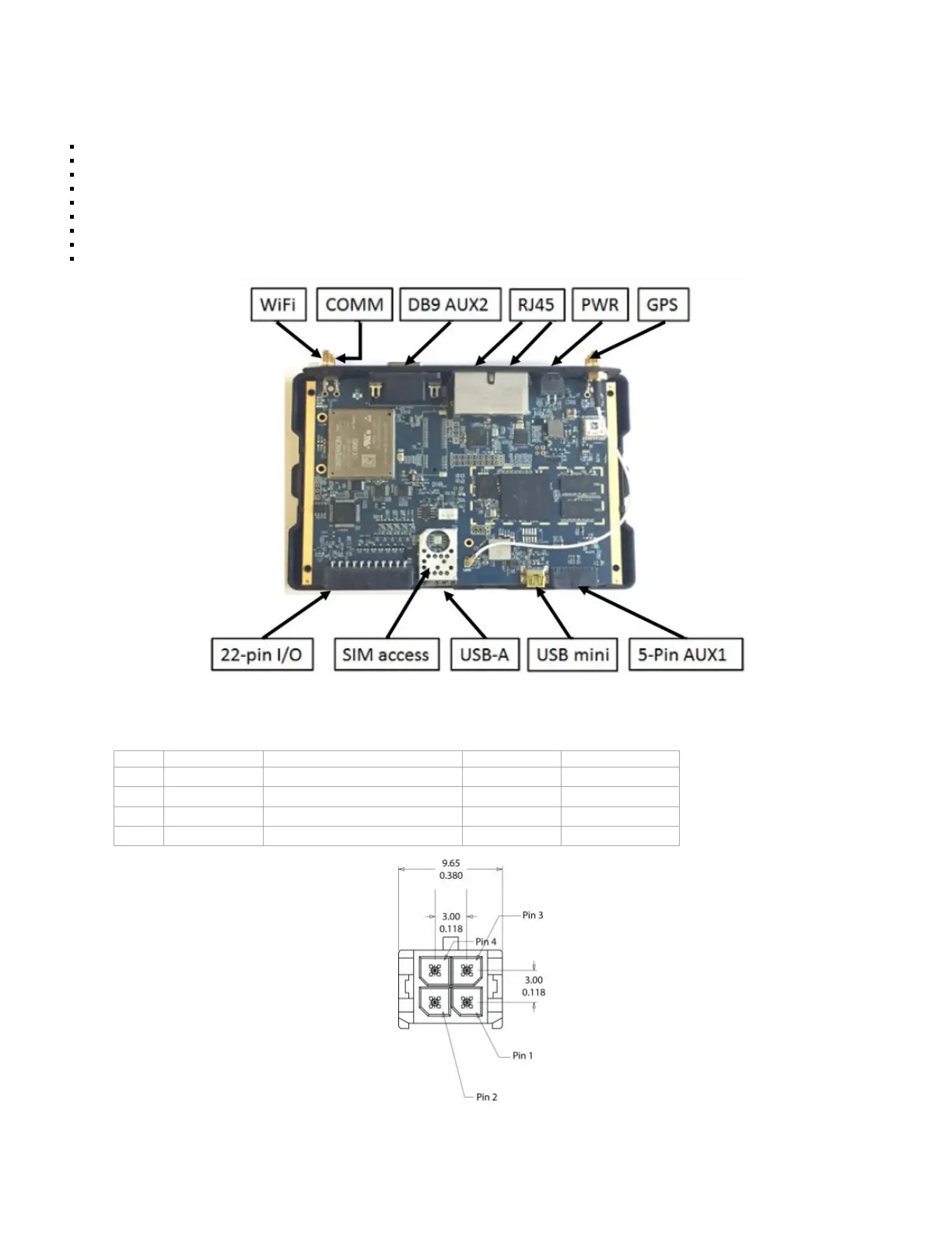
4 LMU-5541™Connectors
The LMU-5541™ offers 22 connectors to access power, I/O, serial communications and other expansion capabilities. These connectors are:
SIM access
SIM Access Slot
Cellular main SMA
External GPS SMA (with tamper monitoring, 3.0v)
External WiFi SMA RP
2X Ethernet10/100 RJ45 USB Host Type A
USB On-The-Go (mini) Serial (RS232/485) DB-9
Serial 5 Pin Molex (switch power TTL Levels) Power, Ignition, I/O 4-Pin Molex
I/O connector 22-Pin Molex
4.1 Power Connector
The LMU-5541™ uses a 4 pin Molex 43045-0402 connector as its power connection. The pin out is as follows:
Pin Signal Name Description 5C888 Color Input or Output
1 VIN Power Red Power / Input
2 GND Ground Black Ground
3 ADC1 Analog to Digital Input 1 Green Input
4 INPUT 0 Input 0 / Ignition Sense – Digital Input White Input
LMU-5541™ Header (looking into LMU)
 Loading...