Output 2: Standard Open Collector Relay Output
Output 3: Standard Open Collector Relay Output
Output 4: Standard Open Collector Relay Output
Output 5: LED Driver Output 1
Output 6: LED Driver Output 2
iButton / 1 Bit Bus
iButton ID Support
1Wire bus with current boost for temperature sensors
4.7.1 Ignition and Inputs
The LMU-5541™ provides up to 7 High/low selectable inputs and one Ignition Sense input.. These inputs are protected from typical vehicle transients and can be
directly connected to most vehicle level logical inputs from 4 volts up to the vehicle power input level (typically 12 VDC). Their input impedance is approximately
10k. One of these inputs is dedicated to sensing the vehicle’s ignition status to provide for flexible power management. The other seven inputs may be used to
sense vehicle inputs such as cooling unit operation, a hidden driver “Panic” switch, taxi on-duty/off-duty meter status or many others.
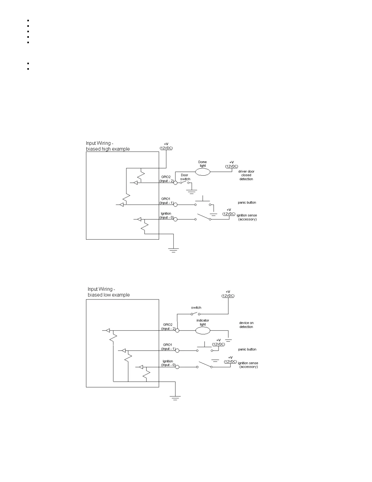
The ignition input is pulled to ground through the 10k resistance, where the other inputs can be configured to be normally High (i.e. pulled to +12v through a
200K10k resistor) or Low (i.e. pulled to ground through a 100K10k resistor). The diagrams below show how to connect the inputs in both a high- and low-biased
configuration:
Sample Input Wiring
4.7.2 Open Collector Outputs
The LMU’s outputs are designed to drive external relays. These outputs provide a high-current, open-collector driver that can sink up to 200 mA each. These drivers
may be used to drive external relays that can then control vehicle functions such as door locks, fuel shut-off valves, sirens and lights. If additional current is required
to drive the relays, external circuitry can be added to source the current. This diagram is a typical use of an output to drive a relay.
 Loading...