2 FACILITIES
24
26
2827 29
25
23
30
15
17 18
20
22
16
19
21
8
9
13 14
10
11
12
1
2
3
4
5
6
7
USER MANUAL
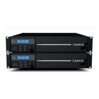
VORTEX 3 QUADRO
P.8
USER MANUAL
VORTEX 3 QUADRO
P.9
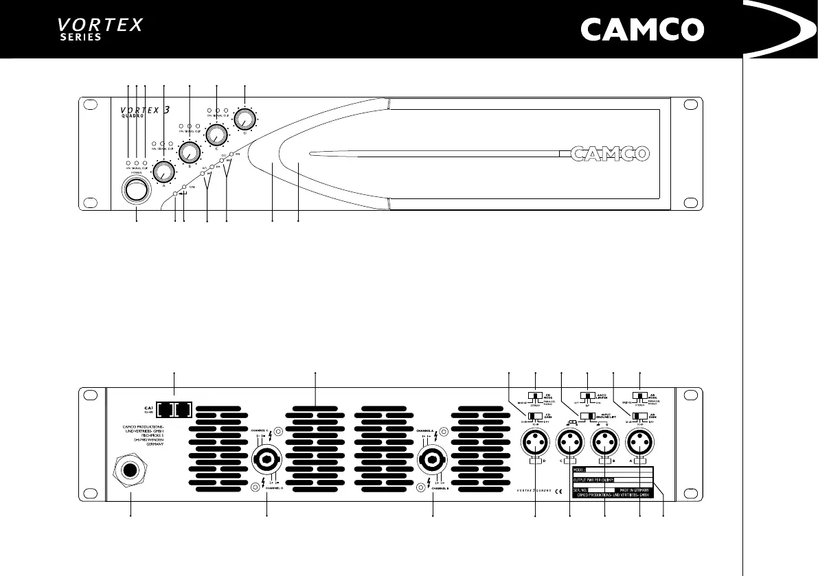
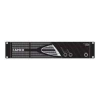
VORTEX 3 QUADRO – The Front
1 On LEDs (multifunctional)
2 Signal LEDs
3 Clip LEDs (multifunctional)
4 Volume Control – Channel A
5 Volume Control – Channel B
6 Volume Control – Channel C
7 Volume Control – Channel D
8 On/Off Switch
9 Enter-Switch (behind Front Panel)
10 CAI Status Indicator
11 Operating Mode Indicators ch. A/B
12 Operating Mode Indicators ch. C/D
13 Removable Air Filter System
14 Cooling Air Inlet Vents
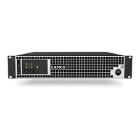
VORTEX 3 QUADRO – The Rear
15 CAMCO Audio Interface (CAI)
16 Cooling Air Outlet Vents
17 Gain Selector ch. C/D
18 Mode Selector ch. C/D
19 Input Ground Lift Switch
20 Limiter Switch ch. A/B/C/D
21 Gain Selector ch. A/B
22 Mode Selector ch. A/B
23 AC Power Cable
24 SPEAKON Outlet ch. C/D
25 SPEAKON Outlet ch. A/B
26 XLR-Line Input ch. D
27 XLR-Line Input ch. C
28 XLR-Line Input ch. B
29 XLR-Line Input ch. A
30 Rating Plate