3INSTALLATION
DO NOT REMOVE MAINS CONNECTOR GROUND
IT IS ILLEGAL AND DANGEROUS
to Pin 1
of the XLRs
USER MANUAL
VORTEX 3 QUADRO
P.12
USER MANUAL
VORTEX 3 QUADRO
P.13
3.4 Cooling
Under normal operation of the power amp, overheating should never be a
problem. The air is taken in from the front and out through the back, it is of
course essential that while the power amp is running air is able to circulate
around it freely.
The temperature of the cooling air will depend on the immediate environment
(e.g. an enclosed rack, direct sunlight) and on whether the front lter is clogged.
If the amp is installed in a case, the open area at the back of the case must be at
least 140 cm². This area should be in line with the amp.
If this can not be achived a forced ventilation system has to be used.
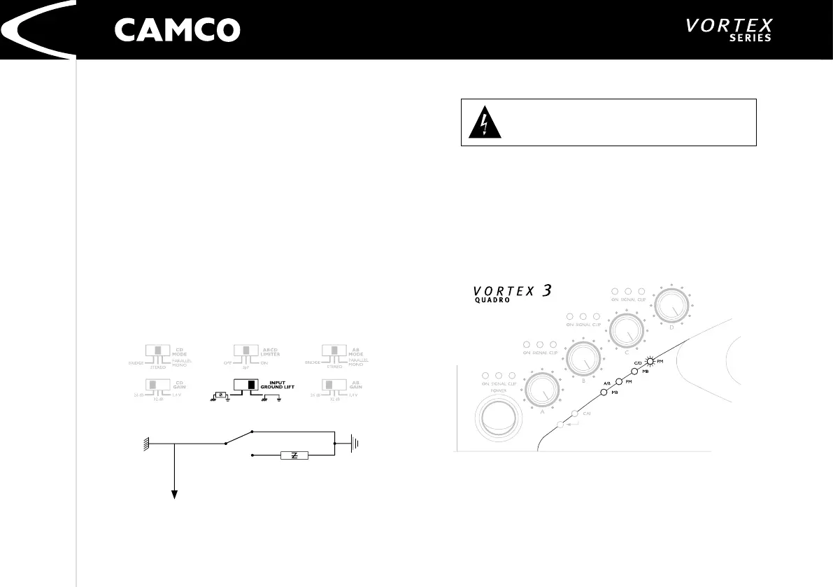
3.5 Ground Lift
The input signal ground (pin 1 for all 4 XLRs) is tied to the ground potential in
the mains supply. Opening the ground lift switch causes this connection to be
broken. This allows ground loops that sometimes occur in practice to be elimi
-
nated. The ground potential of the power amp and therefore of the loudspeaker
outputs is independent of the switch setting and remains at the ground poten
-
tial of the mains supply.
Removing or taping the mains connector ground is illegal and dangerous.
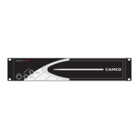
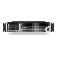
3.6 Mode Indicators
On the front panel there are two pairs of yellow LEDs (A/B, C/D) to indicate the
modes that are set to the ampliers A/B and C/D. In stereo mode none of them
will be lit. In Parallel-Mono the (PM) LED and in Mono-Bridge the (MB) LED will
be lit.
Example:
VORTEX 3 QUADRO
in three channel operation,
A/B is set to stereo (no LED lit) and C/D to parallel-mono mode (PM lit).