4 OPERATION
USER MANUAL
VORTEX 3 QUADRO
P.20
USER MANUAL
VORTEX 3 QUADRO
P.21
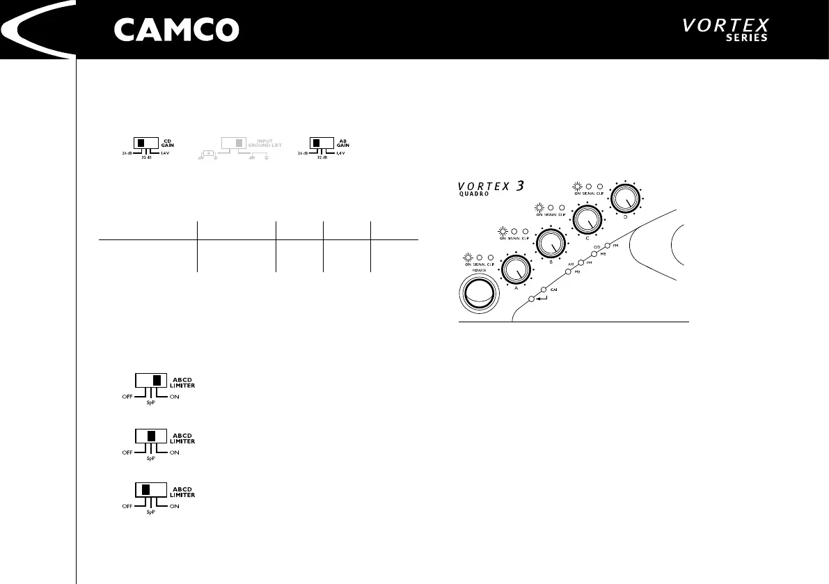
4.2.2 Gain Selector
Two switches on the rear of the VORTEX allows the maximum amplication
attainable to be set directly in the input stage of each amplier (A/B, C/D).
The VORTEX amplier has a 26 dB and 32 dB voltage gain setting along with a
1,4 V sensitivity setting.
Model 26 dB 32 dB 1,4 V
VORTEX 3 QUADRO
4 Ω / 750 W
8 Ω / 450 W
2,75
3,01
1,38
1,51 32,64
4.2.3 Limiter Switch
This switch is located at the rear of the VORTEX. It allows you to set the mode of
the limiter. This limiter affects both channels in both ampliers There are three
modes: (See 4.4.1 Clip Limiter and 4.4.4 Speaker Protect Limiter)
Right position:
Clip Limiter: On
Speaker Protect: On
Middle position:
Clip Limiter: Off
Speaker Protect: On
Left position:
Clip Limiter: Off
Speaker Protect: Off
4.3 Indicators
4.3.1 On LEDs (multifunctional)
Under normal operation, after the amp has started, the green power LEDs are
permanently lit. A variety of different sequences of ashing LEDs are used to
indicate other operating states and errors in one of the channels of the power
amp. (See 6.1 On LED Flashing Sequences)