12 04/2014
© 09/2010 © CAME cancelli automatici s.p.a. - The data and information in this manual may be changed at any time and without obligation on the part of Came Cancelli Automatici S.p.a. to notify said changes.
ITALIANITALIAN
ENGLISH
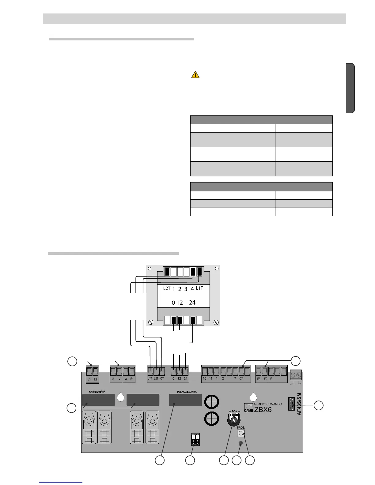
6.1 Technical sheet description
6 - Electronic card
FUSE TABLE
to protect: fuses for:
Electronic board (line) 5 A-F
Accessories 1 A-F
TECHNICAL DATA
Power supply voltage 230 V - 50/60 Hz
Maximum allowed power load 200 W (BX64-BX64B)
300 W (BX68-BX68B)
Power draw when idle 2.6A (BX64-BX64B)
2.4A (BX68-BX68B)
maximum power for 24 V
accessories
20W
8.2 Main components
1. Terminals for connecting the power supply and
gearmotor
2. Line fuses 2x5A
3. 1 A accessories fuse
4. Functions selector
5. Automatic closing time adjuster trimmer
6. LED signal light
7. 10) Button to memorise the radio code
8. Radio frequency card socket
9. Terminals for connecting accessories and
endpoints
Orange
Purple
White
Red
Black
The electronic board is powered by 230V A.C., on terminals
L1-L2, with a max frequency of 50/60Hz.
The command devices and accessories are powered by 24V.
Warning!The accessories must not exceed 20 W overall.
The photocells may be set up for re-opening during closing
(2-C1) or for total stop.
All connections are protected by quick fuses, see table.
The card provides and controls the following functions:
- automatic closing after an opening command;
The available command modes are:
opening / closing (BX-64/BX-68);
- opening / stop / closing / stop (BX-68B);
-opening/closing with maintained action;
- total stop.
Special trimmers regulate:
- the working time for automatic closing;
WARNING: before acting inside the equipment, cut the main power
supply and disconnect the batteries (if they are connected).
Blue
 Loading...