04/2014 © CAME cancelli automatici s.p.a. - The data and information in this manual may be changed at any time and without obligation on the part of Came Cancelli Automatici S.p.a. to notify said changes.
ITALIANITALIANENGLISH
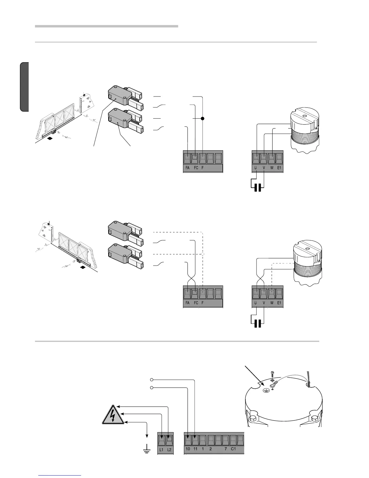
6 Electrical connections
Terminals for powering accessories:
- a. 24V A.C. Overall allowed power: 20W
Power source and accessories
230 V AC powered, 50 / 60 Hz
frequency
Eyelet terminal with screw and washer for ground connection
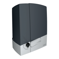
Closing micro-
switch
Gearmotor and endstops
Changes to electrical connections for installing on the right-hand side.
Invert the phases of the (U-V) gearmotor and
(FA-FC) endstops
Opening micro-
switch
Description of electrical connections which are already established for left-hadn isntallation
Condenser
230 V AC motor
Orange
Orange
Red
Red
White
White
 Loading...