173
81,5
40
120
100
60
18
A
B
120 min.
C MAX
47,5
310 max.
200 min.
Page 7 - Manual code: 119DW01EN vers. 5 2016/05 © CAME S.p.A. - The data and information provided in this manual are subject to change at any time without prior notice by CAME S.p.A.
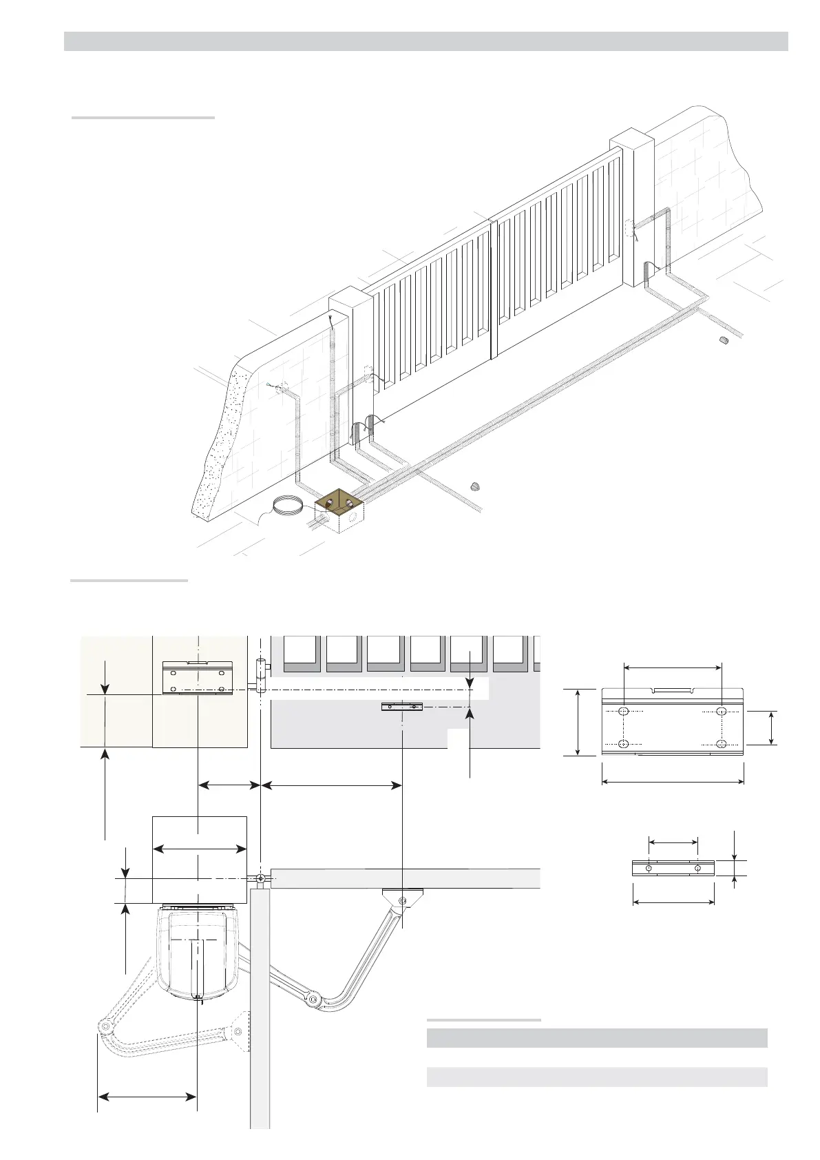
INSTALLATION
⚠
The following illustrations are only examples, given that the space for securing the operator and accessories varies depending on the overall dimensions. The
installation technician is responsible for choosing the most suitable solution.
Installing corrugated tubes
Set up corrugated tubes for the connections coming from the junction box.
N.B. the number of tubes depends on the type of system installed and any accessories.
Two corrugated tubes are required where the FA4024CB operator is installed.
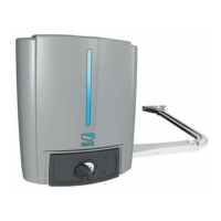
Securing the brackets
N.B. the drawings refer to installation of the left-hand gearmotor. The installation of the right-hand gearmotor is symmetrical.
Determine the fixing point for the gate bracket and calculate the fixing point of the pillar bracket, respecting the values shown in the drawings and table.
Application size (mm)
Leaf opening (°) A C MAX B
90° 140 0 - 200 420
90° 160 - 180 200 380
110° 200 - 220 0 - 50 400