-4-
ITALIANO • ENGLISH • ESPAÑOL
67
67
160
100 60
3
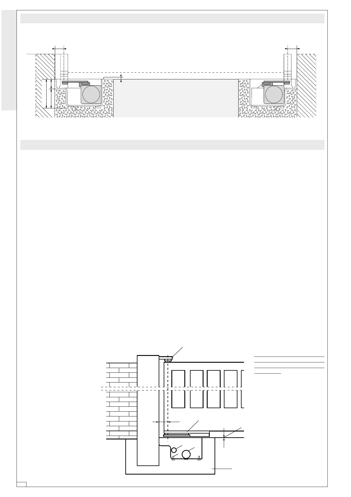
Fig. 2
Fig.3
67
2
5
7
1
6
3
3
Schema di montaggio -
Assembly description
- Esquema de montaje
Installazione -
Installation
- Instalación
- Verificare l’efficenza delle parti fis-
se e mobili della struttura che dovra’
supportare l’automazione;
- Scegliere, in base al tipo di struttura
e di apertura desiderata, l’esatta
posizione del gruppo motore se-
guendo le applicazioni tipo indica-
te;
- Sistemare una battuta d’arresto in
chiusura e in apertura (fig. 4,
pag. 5)
- Eseguire in base alle misure del
gruppo uno scavo di fondazione nel-
la posizione prescelta (Fig. 3);
- Prevedere uno scarico per I’acqua
che eviti, nella fondazione, ristagni
e successive ossidazioni (Fig. 3 -
part. 1);
- La cassetta di fondazione rende la
posa in opera del gruppo agevole e
veloce. Collocare la stessa all’in-
terno dello scavo con il perno alline-
ato al cardine superiore (Fig. 3 -
part. 2), annegarla nel calcestruzzo
(Fig.3 - part. 3) curandone la messa
in bolla e la corretta posizione del
bordo superiore, che dovra sporgere
di 3 millimetri dal livello terra (Fig.
3 part. 4);
- Prevedere il percorso dei cavi elettri-
ci secondo le disposizioni di coman-
do e sicurezza utilizzando I’apposito
foro sulla cassetta (Fig. 3 - part. 5);
- Ingrassare i perni di rotazione della
cassa di fondazione e della leva
attacco cancello prima del montag-
gio;
- Posizionare l'anta del cancello tra il
cardine superiore e la leva perno; il
cardine e la leva perno dovranno
essere in asse tra loro;
- Saldare accuratamente la leva perno
all'anta del cancello realizzando un
fissaggio a tratti di circa 3 o 4 cm.
lungo la superfice di contatto evi-
tando la saldatura in prossimita' dei
fori filettati (Fig. 3 - part. 6).
- Check the efficency of the fixed and moving parts on the structure
designed to support the automation system;
- Determine, on the basis of the type of structure and opening desired, the exact
position of the motor assembly, following the examples shown;
- Place a closing gate jamb as well as a jamb on aperture (fig. 4, pag. 5);
- Dig a foundation trench in the position selected on the basis of the
dimensions of the unit. (Fig. 3);
- Provide suitable water drainage to avoid rust-causing conditions. (Fig. 3 -
part.1);
- The foundation box simplifies and speeds up the installation of the unit:
install it inside the trench with the stud aligned with the top hinge (Fig. 3 -
part. 2); set it perfectly level in concrete (Fig. 3 - part. 3), ensuring the upper
border is in proper position 3 mm. above ground level. (Fig. 3 - part. 4);
- Determine the layout of the power cables in accordance with operating and
safety standards. (Fig. 3 - part. 5);
- Lubricate rotating pins of the foundation casing and of the gate lock lever
before mounting;
- Place the gate door between the upper hinge and the pin lever; the hinge and
the pin lever must be in axis;
- Carefully weld the lever pin to the gate door, making an intermitent seal of
approximately 3 or 4 cm along the contact surface, avoiding welding near
the threaded holes (fig. 3 - part. 6).
Averiguar la eficacia de las partes
fijas y móviles de la estructura
que tendra que recibir la automa-
tización;
- Seleccionar, según el tipo de es-
tructura y de apertura requerida,
la exacta posición del grupo mo-
tor con relación a las aplicaciones
estándar indicadas.
- Colocar un tope en cierre, tambien
en la apertura (fig. 4, pag. 5);
- Efectuar según las medidas del
grupo una excavación de funda-
mentos en la posición escogida.
(Fig.3);
- Proveer al desagüe para que en el
fundamento no haya sucesivamen-
te estancamientos y oxidaciones.
(Fig.3 - part.1);
- La caja de fundamento hace que
la colocación del grupo sea fácil
y rápida: hay que ponerla en el
interior de la excavación con el
perno en línea con la bisagra
superior (Fig. 3 - part.2), rodear-
la de hormigón (Fig.3 - part.3)
cuidando la puesta a nivel, y la
correcta posición del borde supe-
rior, que tendrá que sobresalir de
unos 3 milímetros del nivel de la
tierra. (Fig.3 - part.4);
- Proveer el recorrido de los cables
eléctricos según las disposicio-
nes de control y seguridad. (Fig.3
- part.5);
- Engrase los pernos de rotación de
la caja de cimentación y de la
palanca de unión a la verja antes
del montaje;
- Coloque la hoja de la cancela
entre el gozne superior y la palan-
ca eje; el gozne superior y la
palanca eje deberán quedar en
eje entre sí;
- Suelde muy bien la palanca eje a
la hoja de la cancela, soldándola
por trechos de 3 o 4 cm a lo largo
de la superficie de contacto, evi-
tando soldar cerca de los aguje-
ros roscados (Fig.3 - part.6).

 Loading...


