Page 7 - Manual FA01748-EN - 04/2023 - © CAME S.p.A. - The contents of this manual may be changed at any time and without notice. - Translation of the original instructions
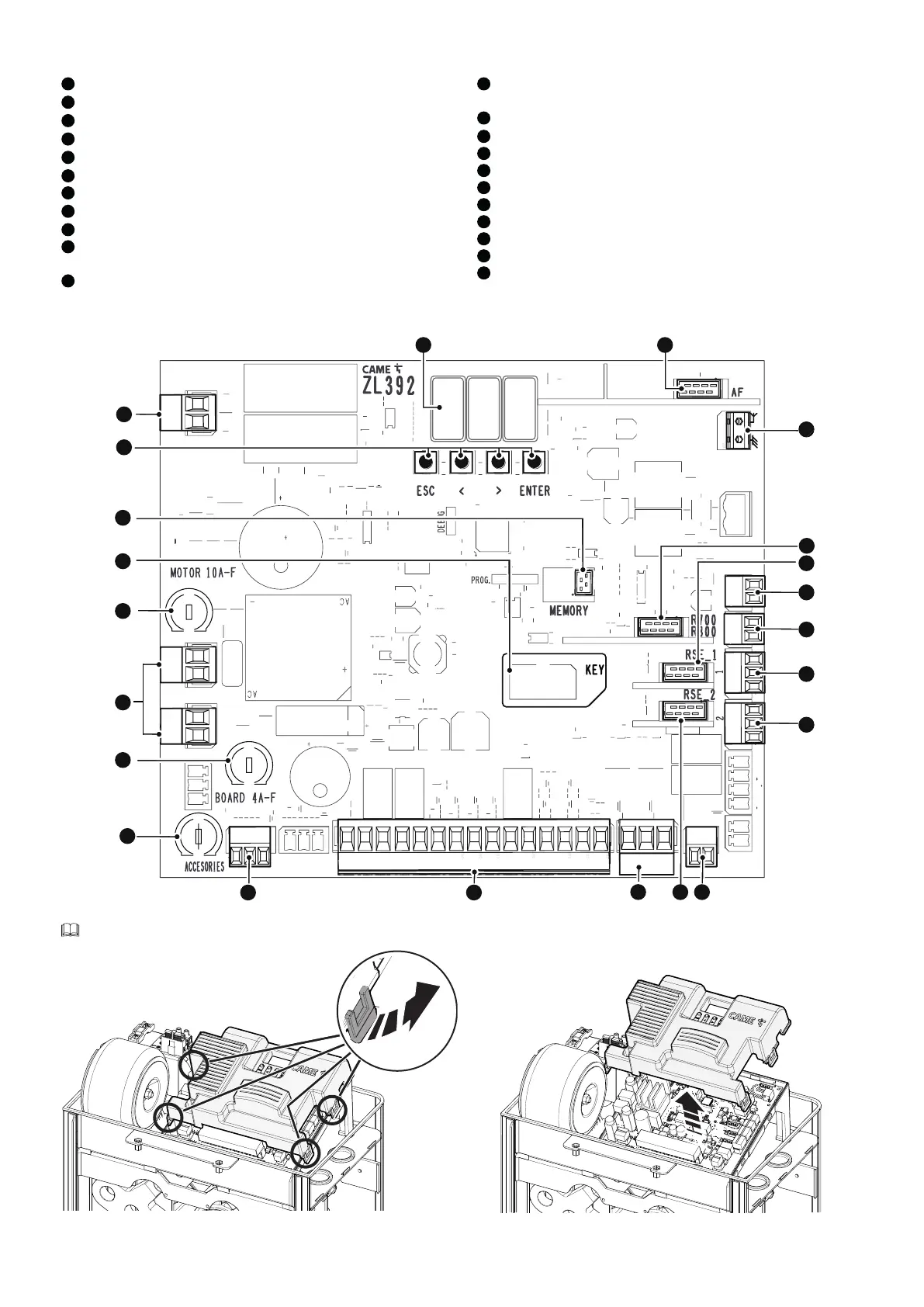
Control board
1
Programming buttons
2
Terminal board for motor power supply
3
Display
4
Connector for plug-in radio frequency card (AF)
5
Terminal board for connecting the antenna
6
Connector for the R700 or R800 decoding card
7
RSE_1 connector for RSE card
8
Terminal board for connecting the keypad selector
9
Terminal board for connecting the transponder selector switch
10
Terminal board associated with the RSE_1 connector for paired, alternate or
CRP connection
11
Terminal board associated with the RSE_2 connector for CRP connection, IO
485 card or Modbus RTU interface
12
Terminal board for connecting the safety microswitch with cover open and
gearmotor released (NC contact)
13
RSE_2 connector for RSE card
14
Terminal board for connecting control and safety devices
15
Terminal board for connecting the encoder
16
Accessories fuse
17
Control board fuse
18
Terminal board for power supply to the control board
19
Motor fuse
20
Connector for CAME KEY*
21
Memory Roll card connector
22
Terminal board for connecting the warning LED strip
NM
AB
S1 GND
A B GND
A B GND
024
+E -
017
TAMPER
10 11 E1 TS 1 2 3 3P 4 5 7 2 CX CY CZ
+R
G
1
3
2
4
5
7
8
9
10
11
12
14
19
15
17
18
21
6
13
16
20
22
Remove the card cover before inserting the cards into the connectors.
 Loading...


