Section01 TECHNICAL MANUAL
Subsection 01 (DYNAMIC POWER STEERING (DPS))
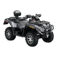
vmr2010-003-024_a
TYPICAL - LEFT SIDE ILLUSTRATED
Step 1: Remove DPS retaining screws (2 each side)
Step 2: Discard conical washers under screw head
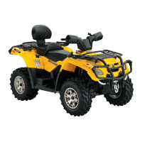
20. Pull up on DPS unit to align the 2 small hexag-
onal forming screws with the extraction holes
in the DPS mounting bracket, then remove the
DPS unit from the bracket.
vmr2010-003-025_a
TYPICAL - RIGHT SIDE ILLUSTRATED
1. Hexagonal forming screws (1 each side)
2. Extraction holes
3. DPS unit
NOTE: As you pull the DPS unit from the frame
support, the 2 tie rod ends should release from
thepitmanarm. Becarefulnottoloosethehard-
ened steel washers on the tie rod ends.
DPS Unit Installation
NOTICE
The following procedure MUST be
followed as specified. Failure to do so may re-
sult in steering column/DPS misalignment and
poor DPS operation due to an induced erro-
neous torque on the DPS shaft.
1. If installing a new DPS unit, install the two M5
hexagonal forming screws on the mounting
flange of the DPS unit.
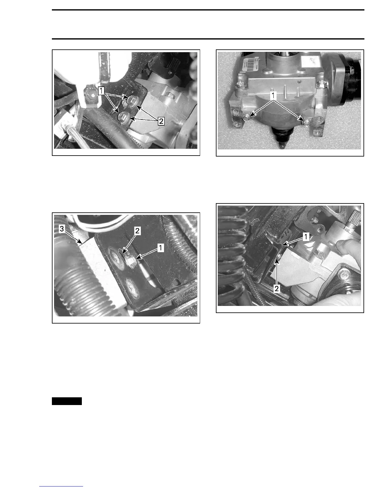
vmr2010-003-026_a
1. Hexagonal forming screws
2. Position the DPS unit on the frame DPS mount-
ing bracket by engaging the two hexagonal
forming screws in the slots provided in the
bracket.
vmr2010-003-027_a
1. DPS mounting bracket
2. Engage hexagonal forming screw on DPS unit here
3. Engage the 2 tie rod ends in the pitman arm
as you lower the DPS unit on it's mounting
bracket.
NOTE: Ensure both tie rod ends has a hardened
steel washer on it.
vmr2010-003 17