Section01 TECHNICAL MANUAL
Subsection 01 (DYNAMIC POWER STEERING (DPS))
vmr2010-003-032
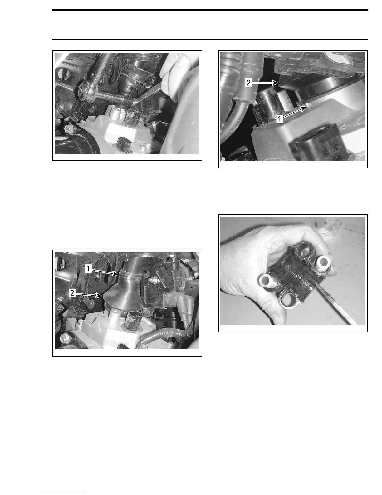
Pull bellows down over steering column bolt and
edge of DPS unit housing extension. Secure bel-
lows using the appropriate locking tie.
NOTE: Ensure the locking tie is on the tube part of
the steering column, not on the forged end. Bel-
lows should cover end of ring flange on DPS unit
but not cover the drainage hole at the bottom of
the ring flange. Do not install a locking tie on the
DPS end of the bellows. Lower portion of bellows
MUST remain floating over the DPS housing.
vmr2010-003-016_a
1. Locking tie location
2. Steering column bellows
vmr2010-003-033_a
1. Drainage hole in DPS ring flange
2. Steering column bellows
9. Apply XPS SYNTHETIC GREASE (P/N 293 550 010)
totheinsideofbothsteeringcolumnhalfbush-
ings.
vmr2010-003-034
10.Looselysecurethesteeringcolumntoits
frame support by installing the following parts
to provide side to side alignment of steering
column.
– Half bushings (x2)
– Metal sleeves between bushings (x2)
– O-ring seals (x2)
– M8 hexagonal screws (x2)
– M8 elastic nuts (x2).
NOTE: Do not install shims a
nd do not torque the
fasteners at this time. H
and tighten only. Steering
column must not be draw
n in towards the column
support.
vmr2010-003 19