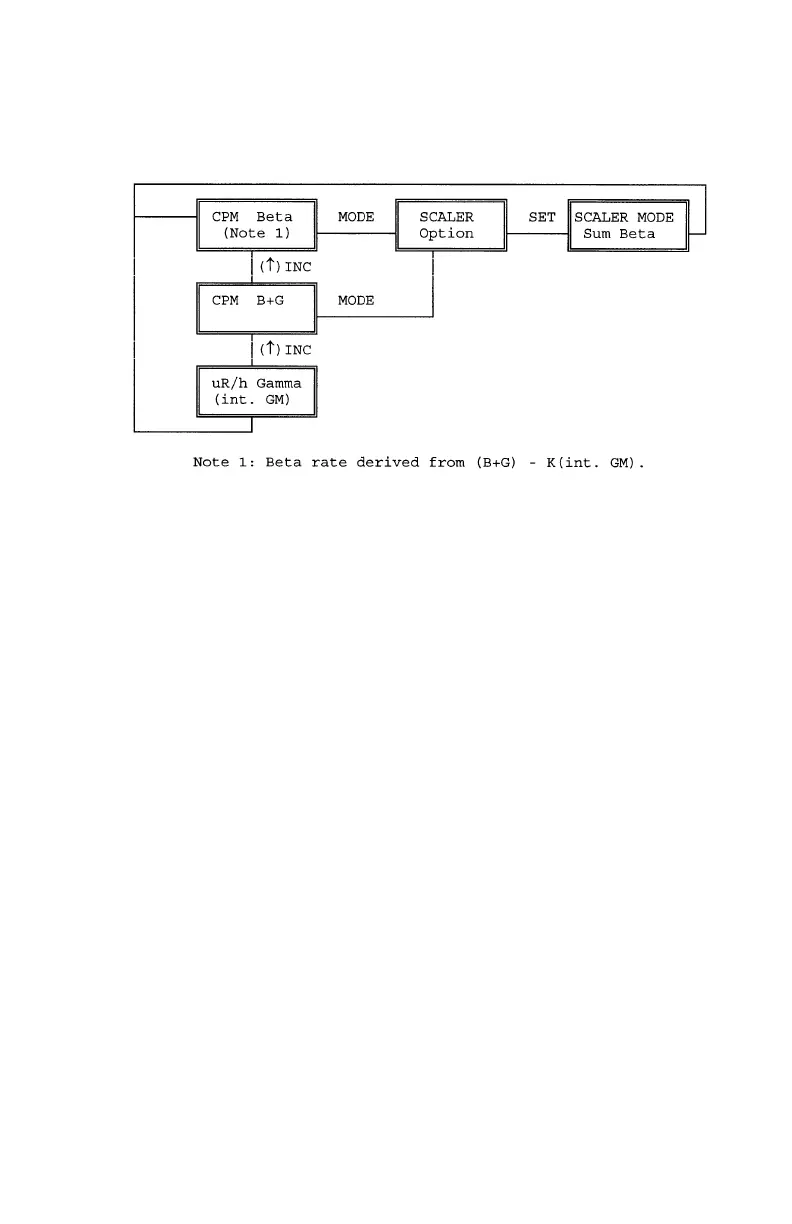
BP100 Beta Probe Displayed Function Flow Diagram
2.2.5.3 GAMMA PROBE, BGP100
1. With the survey meter turned OFF, connect the probe cable to the 7-pin
connector on the probe and the other end of the cable to the ADM300 7-pin
connector.
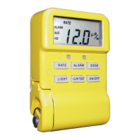
2. Turn the survey meter power ON. The unit displays "Please Wait", then units of
measurement. "RaGm" (Rate Gamma) is shown in place of the usual "Rate" to
indicate that an external gamma probe is attached.
Note: If the unit does not indicate probe is attached, refer to Chapter 3, Operator
Maintenance, for trouble shooting procedures.
The unit begins to monitor Gamma radiation using the external probe.
The two internal G-M tubes are de-activated in this configuration. Refer to the
Gamma probe's functional flow diagram for available modes.
3. Press and release AUDIO to activate the sounder as desired.
4. Turn off ADM300 and disconnect probe.
31