CandCNC
Page 17
Finding the correct connections.
The first signal you need to identify and locate is the Raw Arc Volts (Raw Tip Volts). This is
the voltage between the Electrode and the Workclamp. The Hypertherm 1000 thru 1650
series have two spade terminals (J15 and J16) that are for easy connection of Raw Arc Volts.
On later models (45/65/85/105/125) WITHOUT the internal voltage divider, the location of the
Raw Arc Volts is not as obvious but they have Field Service Bulletins where they give detailed
directions on finding the Raw Arc Volts. Our manual covers connection to the PowerMax
1000, 1250 and 1650 as well as the PowerMax 45 and PowerMax 65/85/105 with the optional
CPC connector.
https://www.hypertherm.com/Xnet/library.jsp/null is a search page where you can enter your
model number and then search the FSBs. The files are in PDF format.
For other brands of plasma units or a model not designed to be automated the search for
connection points may be a little more difficult but not impossible. The key is the leads going
to the torch cable. On most plasma units you can locate these signals by opening the unit
(POWER DISCONNECTED!) and visually tracing the wires coming from the plasma torch.
The Workclamp will be connected to a stud or terminal inside and is pretty easy to identify. It
is the POSITIVE (+) side of the circuit. The Electrode side goes up the plasma cable to the
torch head. It will be one heavy wire or a series of smaller gauge (12ga or larger) stranded
wires of the same color and they will all connect to the same electrical spot (bus) inside the
plasma. In a lot of units these wires are all solid WHITE in color but do not use color as your
clue. Some plasma manufacturers provide block level schematics in their use or service
manual that give wire colors (and in some cases terminal numbers and locations).
WHEN YOU HAVE LOCATED THE WORKCLAMP AND ELECTRODE WIRES IN THE UNIT:
Using a two conductor wire (18-22 ga) [not supplied] with insulation rated to 400V or more
crimp on two ring or fork terminals. USE WIRES OF TWO DIFFERENT COLORS and long
enough to reach the RAV-02 Card using an indirect route (give yourself extra wire). Run the
first color wire (red or the brightest color) to where the WORKCLAMP attaches. Normally that
will be a heavy bus bar with other smaller wires attached. If it is a single large stud you will
need a ring terminal that will fit over the stud. That will be your positive (+) wire.
Use the other wire color and run a connection using a ring or fork terminal to where the
ELECTRODE wires attach.
Carefully route both wires from their connection points over to where they will attach at spade
inputs on the edge of the RAV-01 Card. Keep the wires away from other high voltage wires or
components on the circuit board. Use nylon wire ties to secure the wires to other wire bundles
or to the chassis. DO NOT WIRE TIE THEM TO COMPONENTS ON THE PC BOARDS. DO
NOT USE LOW VOLTAGE WIRES LIKE THOSE USED FOR WIRING PHONES OF
NETWORKS.
CONNECTING to YOUR PLASMA
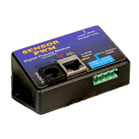
RAV-01 Raw Arc Voltage Divider Option
DTHCIV1-14_2
E
 Loading...