PC400 / PC410 l User’s Manual
12
Chapter 1: Product Introductions
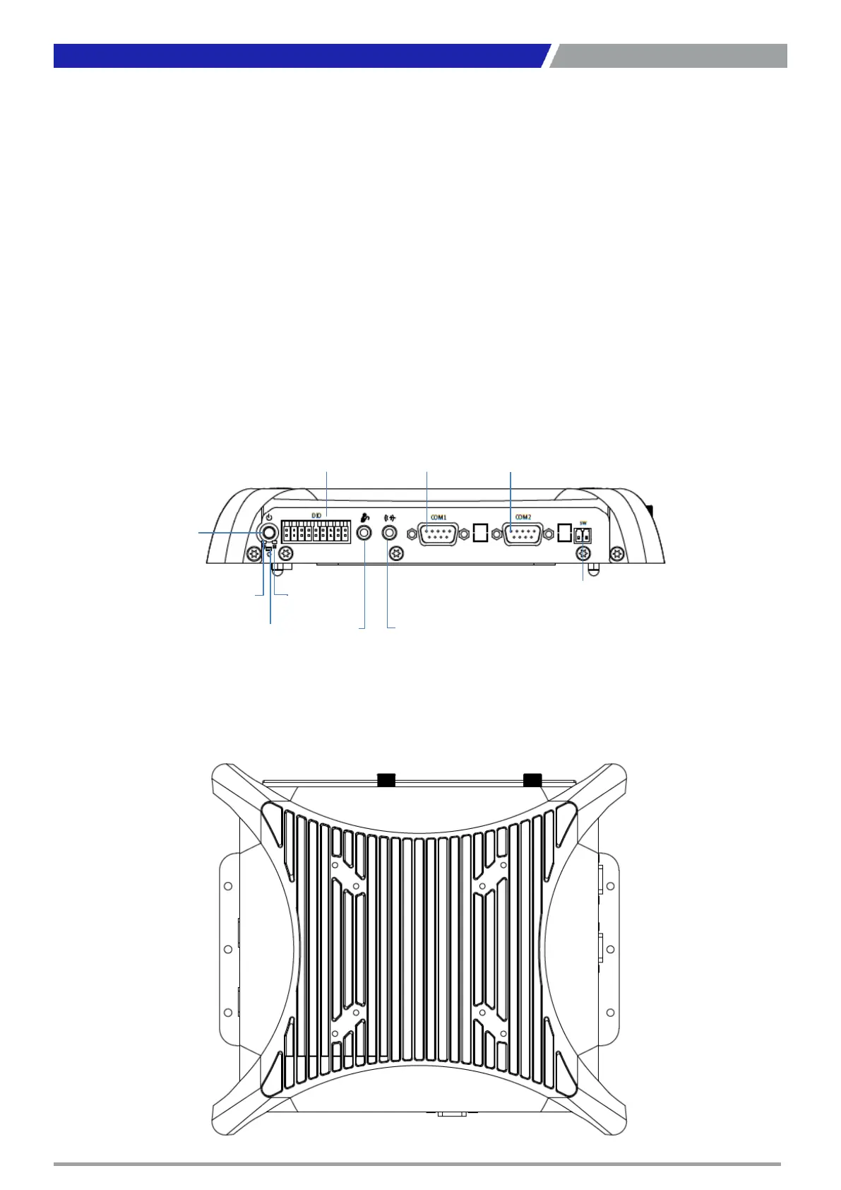
Side (Left)
ATX power on/off switch
Press to power-on or power-off the system
Power LED
Indicates the power status of the system
HDD LED
Indicates the status of the hard drive
Reset switch
Press to reset the system
Digital I/O Terminal Block
The Digital I/O terminal block supports 8 digital
input and 8 digital output
Line-out
Used to connect a speaker
Mic-in
Used to connect a microphone
Remote Power on/off Terminal Block
Used to plug a remote power on/off terminal
block
COM port
COM1 ~ COM2 support RS232/422/485 serial
device
ATX Power
on/off Switch
Power LED HDD LED
Reset
Digital I/O
Mic-in Line-Out
COM 1 COM 2
Remote Power on/off
Top
VESA Mounting Hole
These are mounting holes for VESA mount (75x75mm and 100x100mm)
 Loading...