PC400 / PC410 l User’s Manual
PC/Car Mode
Select Switch
Car Mode Delay
Time Setting Switch
AT/ATX Mode Select Switch COM3 COM4
11
1.3 System I/O
1.3.1 PC400
Chapter 1: Product Introductions
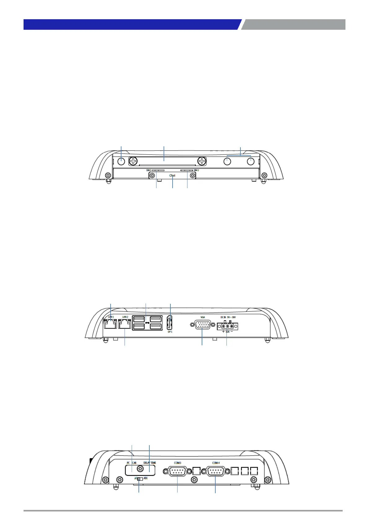
Rear Panel
DC IN
Used to plug a DC power input with terminal
block
VGA
Used to connect an analog VGA monitor
DisplayPort
Used to connect a DisplayPort monitor
USB 3.0 port
Used to connect USB 3.0/2.0/1.1 device
LAN port
Used to connect the system to a local area
network
Front Panel
Removable HDD Bay
Used to inserts a 2.5” HDD device
Antenna hole
Used to connect an antenna for optional Mini-
PCIe WiFi module
SIM Card Socket
Used to insert SIM card
CFast Socket
Used to insert CFast card
Removable HDD Antenna HolesAntenna Holes
SIM 1 SIM 2CFast
DC-INVGA
DisplayPortUSB 3.0LAN 1
LAN 2
Side (Right)
COM port
COM3~4 support RS232/422/485 serial device
PC/CAR mode select switch
Used to select PC or CAR power mode
DELAY TIME switch
Used to select Car power turn off delay-time
AT/ATX mode select switch
Used to select AT or ATX power mode
 Loading...