EasyManuals Logo
Home>C&T>Control Unit>PC400 Series

C&T PC400 Series User Manual

Default Icon
71 pages
To Next Page IconTo Next Page
To Previous Page IconTo Previous Page
Page #24 background imageLoading...
Page #24 background image
PC400 / PC410 l User’s Manual
24
2.4 Connectors Definitions
Chapter 2: Switches and Connectors
24
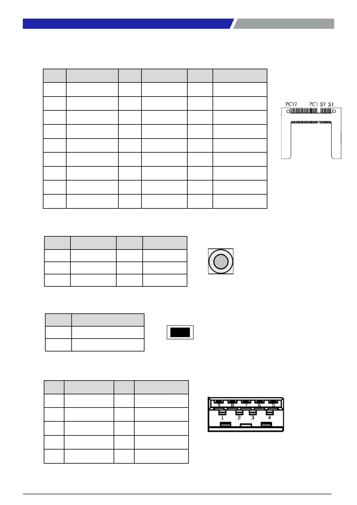
CFAST1_2: CFast Socket
Chapter 2: Switches and Connectors
Pin Definition Pin Definition Pin Definition
S1 GND PC1 NC PC10 NC
S2 SATA_TXP1 PC2 GND PC11 NC
S3 SATA_TXN1 PC3 NC PC12 NC
S4 GND PC4 NC PC13 +3.3V
S5 SATA_RXN1 PC5 NC PC14 +3.3V
S6 SATA_RXP1 PC6 NC PC15 GND
S7 GND PC7 GND PC16 GND
PC8 NC PC17 NC
PC9 NC
PWR_SW2: Power Button
Pin Definition Pin Definition
1 NC 4 GND
2
Power Button
5 NC
3 NC 6 GND
RESET2 : Reset Button
Pin Definition
1 RESET
2 GND
USB3.0 Connector, Type A
Pin Definition Pin Definition
1 +5V 6 USB3_RX+
2 USB2_D- 7 GND
3 USB2_D+ 8 USB3_TX-
4 GND 9 USB3_TX+
5 USB3_RX-

Questions and Answers:

Question and Answer IconNeed help?

Do you have a question about the C&T PC400 Series and is the answer not in the manual?

C&T PC400 Series Specifications

General IconGeneral
BrandC&T
ModelPC400 Series
CategoryControl Unit
LanguageEnglish