EasyManuals Logo
Home>C&T>Control Unit>PC400 Series

C&T PC400 Series User Manual

Default Icon
71 pages
To Next Page IconTo Next Page
To Previous Page IconTo Previous Page
Page #25 background imageLoading...
Page #25 background image
PC400 / PC410 l User’s Manual
25
Chapter 2: Switches and Connectors
25
Chapter 2: Switches and Connectors
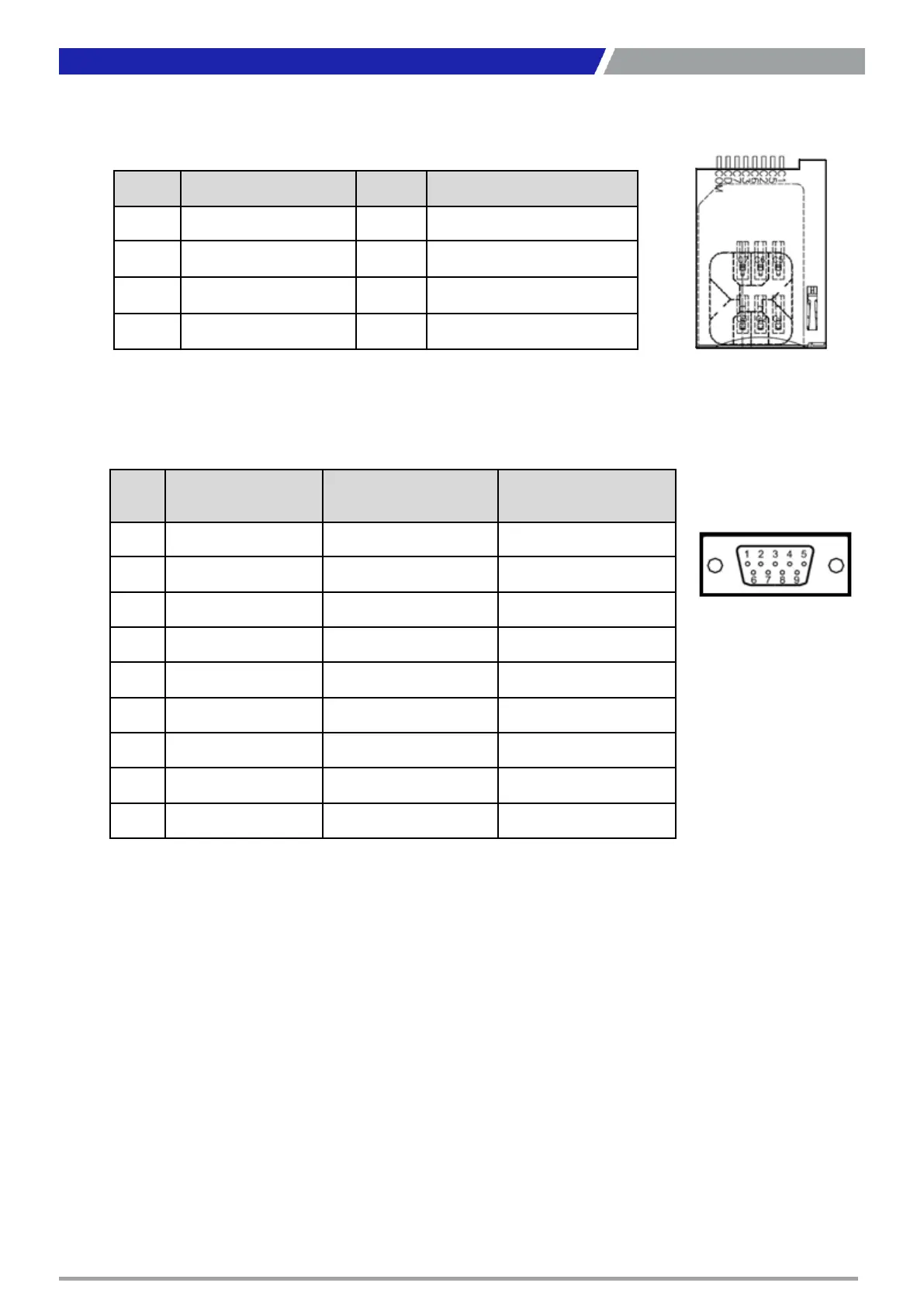
SIM1, SIM2: SIM Card Socket
Pin Definition Pin Definition
C1 UIM_PWR C6 UIM_VPP
C2 UIM_RESET C7 UIM_DATA
C3 UIM_CLK CD NC
C5 GND COM GND
COM: RS232 / RS422 / RS485 Connector
Connector Type: 9-pin D-Sub
Pin RS232 Definition
RS422 / 485 Full
Duplex Definition
RS485 Half Duplex
Definition
1 DCD TX- DATA-
2 RxD TX+ DATA+
3 TxD RX+
4 DTR RX-
5 GND GND GND
6 DSR
7 RTS
8 CTS
9 RI

Questions and Answers:

Question and Answer IconNeed help?

Do you have a question about the C&T PC400 Series and is the answer not in the manual?

C&T PC400 Series Specifications

General IconGeneral
BrandC&T
ModelPC400 Series
CategoryControl Unit
LanguageEnglish