PC400 / PC410 l User’s Manual
26
Chapter 2: Switches and Connectors
26
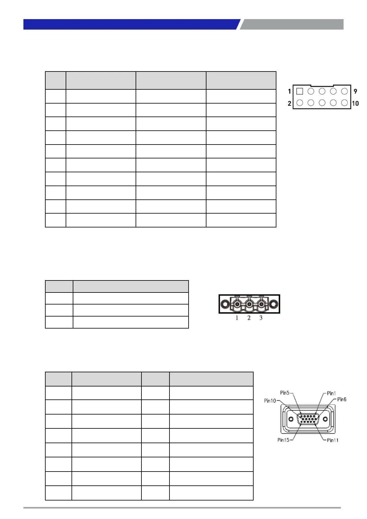
COM: RS232 / RS422 / RS485 Connector
Connector Type: 2X5 10-pin box header, 2.54mm pitch
Pin RS232 Definition
RS422 / 485 Full
Duplex Definition
RS485 Half Duplex
Definition
1 DCD TX- DATA-
2 DSR
3 RxD TX+ DATA+
4 RTS
5 TxD RX+
6 CTS
7 DTR RX-
8 RI
9 GND GND GND
10 NC NC NC
DC_IN1: DC Power Input Connector (+9~50V)
Connector Type: Terminal Block 1X3 3-pin, 5.0mm pitch
Pin Definition
1 +9~50VIN
2 Car power detect (ACC in)
3 GND
VGA: Standard VGA Connector
Connector Type: 15-pin D-Sub
Pin Definition Pin Definition
1 RED 9 +5V
2 GREEN 10 S_GND
3 BLUE 11 NC
4 NC 12 SDA
5 GND 13 HSYNC
6 R_GND 14 VSYNC
7 G_GND 15 SCL
8 B_GND
 Loading...