PC400 / PC410 l User’s Manual
14
Chapter 1: Product Introductions
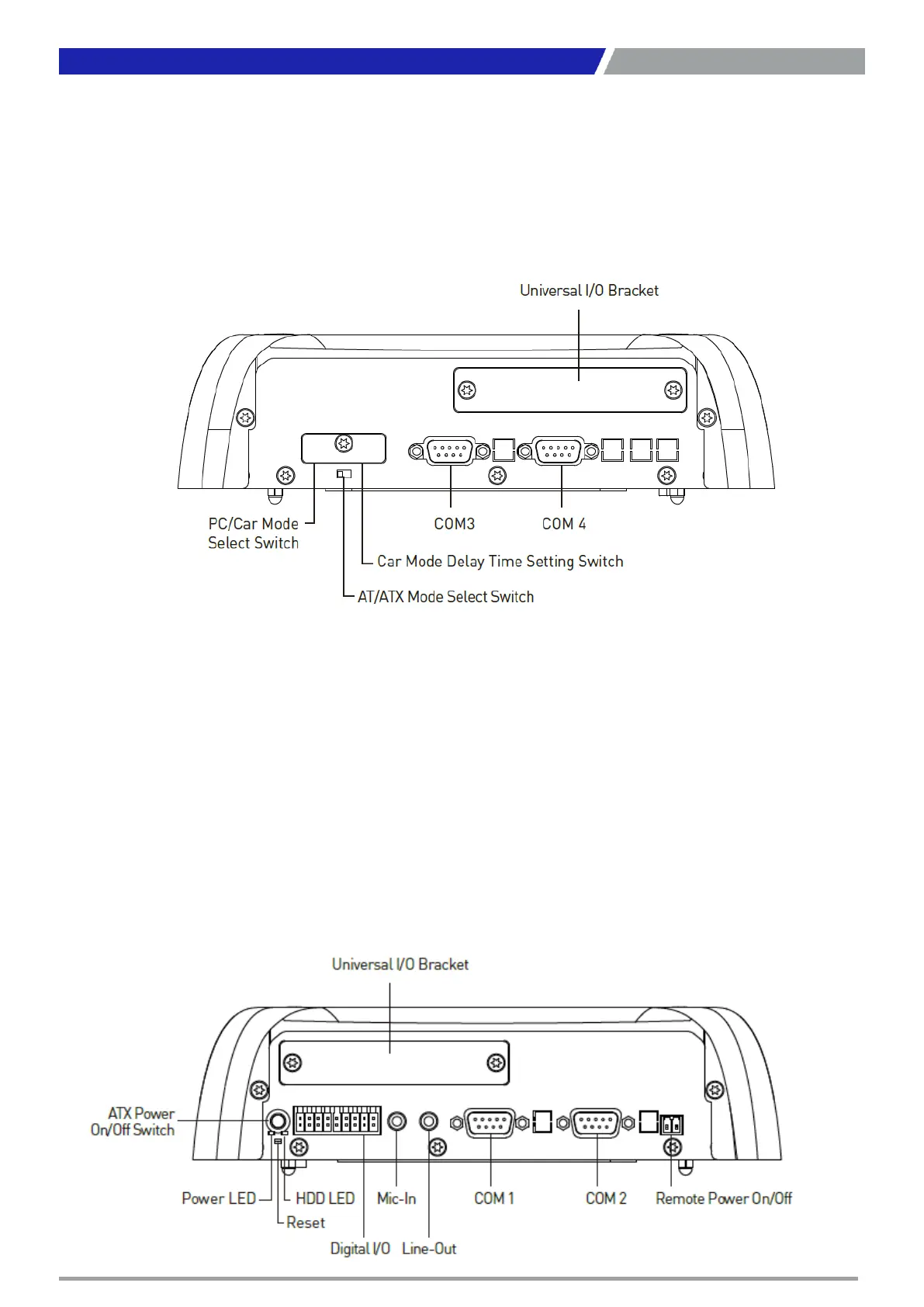
Side (Left)
ATX power on/off switch
Press to power-on or power-off the system
Power LED
Indicates the power status of the system
HDD LED
Indicates the status of the hard drive
Reset switch
Press to reset the system
Digital I/O Terminal Block
The Digital I/O terminal block supports 8 digital
input and 8 digital output
Line-out
Used to connect a speaker
Mic-in
Used to connect a microphone
Remote Power on/off Terminal Block
Used to plug a remote power on/off terminal
block
COM port
COM1 ~ COM2 support RS232/422/485 serial
device
Universal I/O Bracket
Used to customized I/O output
Side (Right)
COM port
COM3~4 support RS232/422/485 serial device
PC/CAR mode select switch
Used to select PC or CAR power mode
DELAY TIME switch
Used to select Car power turn off delay-time
AT/ATX mode select switch
Used to select AT or ATX power mode
Universal I/O Bracket
Used to customized I/O output
 Loading...