14
MS
MS
1
12
16
MS
MS
MS
15
13
3
4
5
6
8
9
2
11
MS
7
10
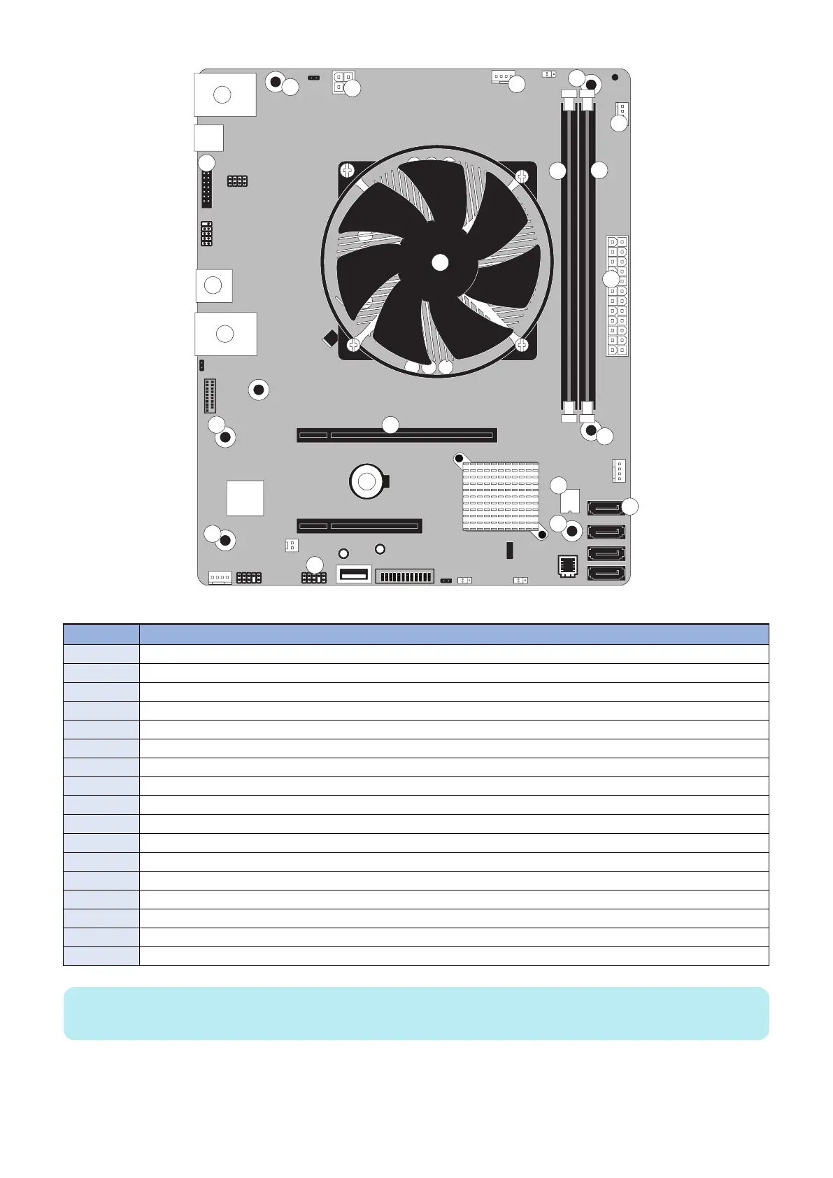
Figure 13: Diagram of the motherboard
No. Name
1 HDD data connector (SATA0)
2 Security chip (J23)
3 Battery (CR1)
4 Printer interface board (PCIEx16)
5 Power button pins (J11)
6 DIMM-A0
7 DIMM-B0
8 Crossover Ethernet port / Type A USB3.0 ports (x2)
9 Type A USB2.0 connector (x2)
10 Type A USB2.0 ports (x2) / Network port (RJ-45)
11 CPU and cooling assembly MS Mounting screws
12 24-pin power connector (J24)
13 4-pin power connector (PWRCONN1)
14 CPU fan connector (CPU FAN J16)
15 FRONT FAN connector (J30)
16 Service board connector (Port 80 Header) (EFI GPIO Header, J4)
MS Mounting screws
NOTE:
Any connectors not listed are not used.
■ Removing the motherboard
Before you remove the motherboard, you must remove:
3. REPLACING PARTS
26