8. Check the 10-pin power button cable that connects the printer interface board (J351) and the motherboard (J11).
Make sure that the cable is intact.
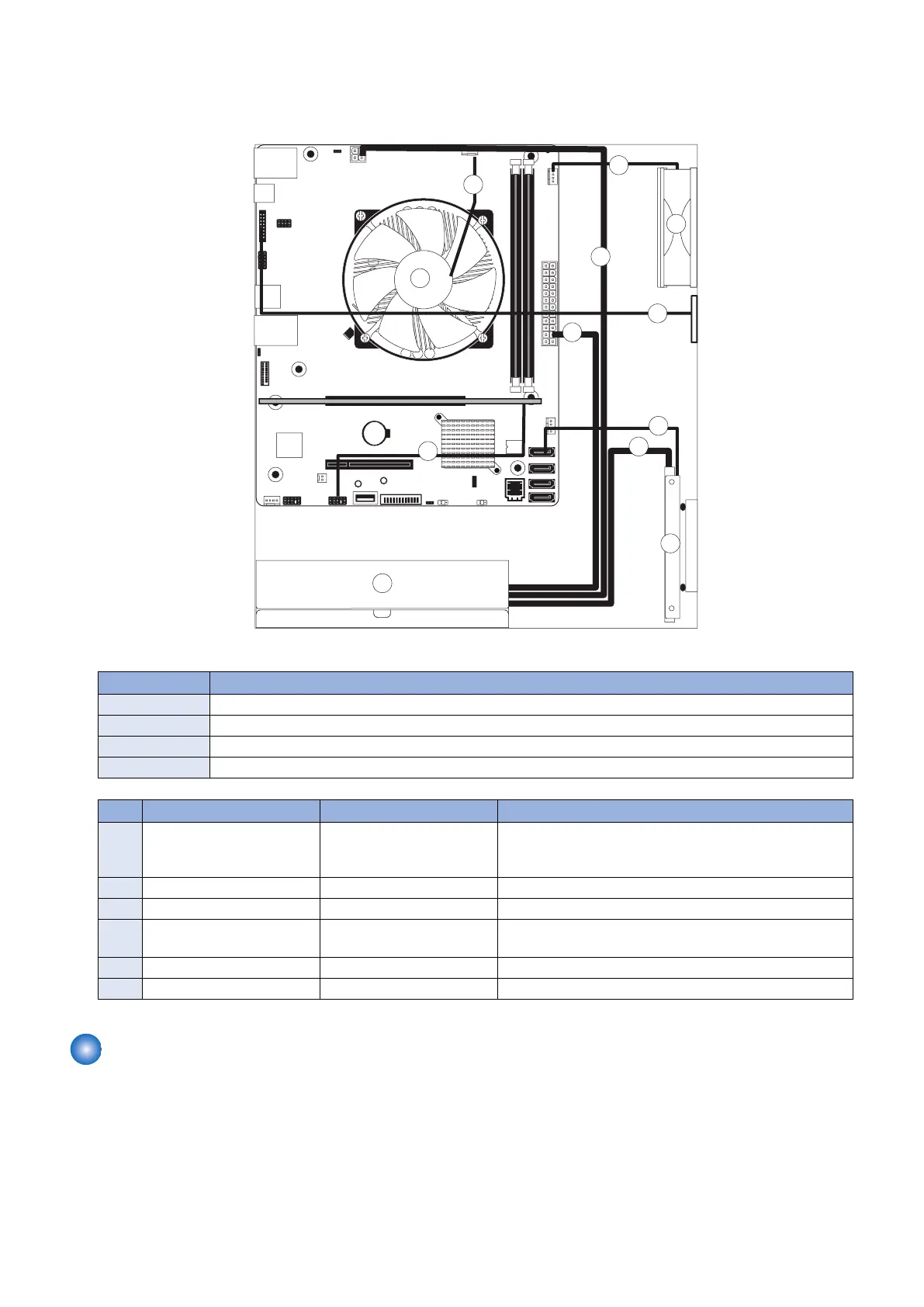
The following diagrams illustrate the internal cable connections between hardware components and the motherboard.
Figure 8: imagePRESS Server internal cable connections
No. Name
A HDD
B Power supply
C Chassis fan
D CPU fan
No. Cable key From To
1 Power supply cables Power supply a. SATA power connector-HDD
b. 4-pin power connector (PWRCONN1)
c. 24-pin power connector (J24)
2 10-pin power button cable Printer interface board (J351) J11 connector on motherboard
3 HDD data cable HDD data connector SATA0 connector on motherboard
4 Service board cable Service board connector Port 80 Header (EFI GPIO Header) connector on mother-
board(J4)
5 CPU fan cable CPU fan CPUFAN connector on motherboard (CPU FAN J16)
6 Chassis fan cable Chassis fan FRONT FAN connector on motherboard (J30)
Removing and replacing imagePRESS Server components
Before replacing costly components, be sure to verify the connections between the printer and the imagePRESS Server. Also,
verify the connections of each replaceable imagePRESS Server component. For more information about troubleshooting, see
“5. TROUBLESHOOTING” on page 67.
The following sections describe how to remove and install replaceable parts on the imagePRESS Server:
• Printer interface board
• DIMM
• Battery
• Motherboard
3. REPLACING PARTS
20