Chapter 1
1-53
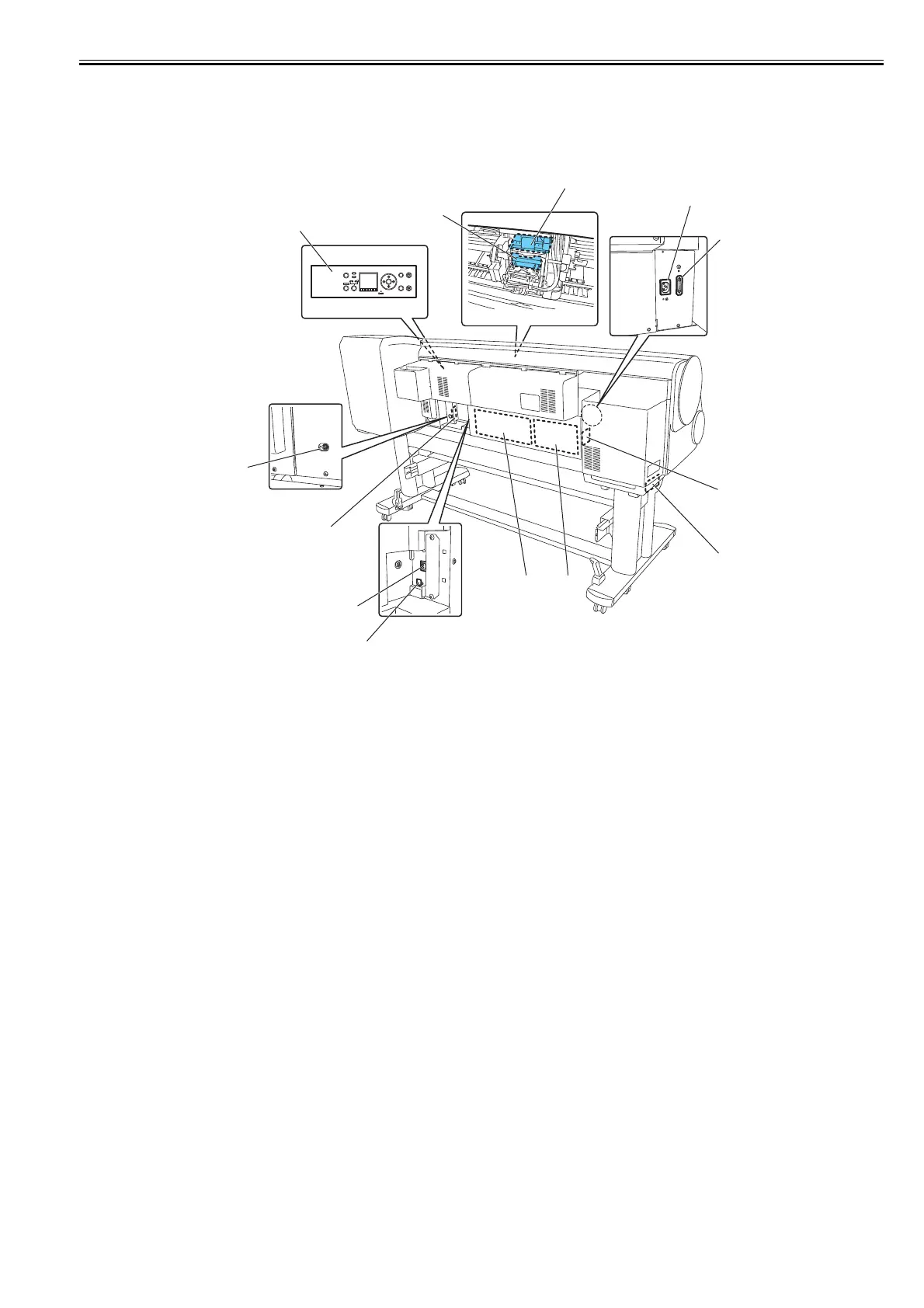
1.7.1.3 Electric Parts
0020-5474
The electrical unit of the printer is activated when connected to the AC power supply.
At the rear of the printer are the main controller, power supply, interface connector, and optional media take-up unit connector. The head relay PCB and carriage
relay PCB are incorporated in the carriage unit, and the operation panel is located on the upper right cover.
When servicing the printer with the cover removed, be extremely careful to avoid electric shock and shorting contacts.
F-1-39
[1] Operation panel [8] Power supply PCB
[2] Carriage relay PCB [9] Main controller PCB
[3] Head relay PCB [10] Ethernet connector
[4] AC inlet [11] USB port
[5] Lower roll unit connector(iPF851/850/841/840/825/820) [12] Media take-up relay PCB(iPF831/830/815/810)
[6] Lower roll unit relay PCB(iPF851/850/841/840/825/820) [13] Media take-up unit connector(iPF831/830/815/810)
[7] lower roll unit PCB(iPF851/850/841/840/825/820)
Power
Online Data
Menu
Message
Information
Load/Eject
Cleaning
(3sec.)
Stop
(1sec.)
[8]
[9]
[12]
[11]
[7]
[6]
[4]
[2]
[3]
[5]
[1]
[13]
[10]
 Loading...