4
2.0 CONTENTS
The contents of the shipping container should include
the following:
Precise® LTM Complete Kit
(1) Precise® LTM Unit
(1) 20’ Fiber Cartridge
(1) Fiber Stripper Tool
(1) Fiber Cleaver
(1)
Package of (20) Disposable Handpiece
Tips- Straight
(2)
Package of (20) Disposable Handpiece
Tips- 60°
(1) Handpiece- Autoclavable
(1) Laser Key
(1) Wireless Foot Pedal
(1) 9 Volt Lithium Battery
(1) Power Supply
(1) Power Cord
(3) Protective Glasses
(1) Precise® LTM Operator’s Manual
(1) Precise® LTM Chairside Guide
(1) Danger - Laser in Use Signage
2.1 REMOVING THE LASER FROM THE PACKAGING
Please do not attempt to unpack the laser and install the various
components without reading this section rst. If you are unsure
about any aspect of the assembly, call your authorized dealer
representative for assistance. Though highly unlikely, you may need
to return the laser for service or repair and the shipping container
you received with your laser has been especially designed to
transport the laser.
LASER ASSEMBLY INSTRUCTIONS SUMMARY
1. Attach the laser’s power cord and place the plug into the
wall receptacle.
2. Install foot pedal battery. (See Section 2.2.3)
3. Attach remote interlock, if desired (not required).
4. Check the laser stop button to see that is has been
pressed.
5. Turn on the power switch on the back of the unit.
NOTE: When the power cord is plugged in, the power
switch is turned on, and the laser stop is released, the key
will turn the unit on.
6. Place the key into the key switch receptacle and turn the
key to the right (clockwise). The control console should
light up.
2.2 ASSEMBLING THE LASER
Each of the following items should be inspected, inserted into the
appropriate receptacle, and when applicable, locked using the
locking hub.
SECTION 2: BEFORE OPERATING YOUR LASER
1
6
5
4
3
2
Figure 1
7
8
9
Figure 2
Figure 3
3
5 POWER
DECREASE
FIBER
RETRACT
2 READY
KEY
FIBER
EXTEND
3 & 4
MODE
KEY
7 PROGRAM
KEY
6 AIMING
BEAM
1
7
5
2
4
6
5 POWER
INCREASE
89
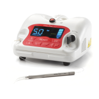
LED DISPLAY AND CONTROL PANEL
1. Laser on Indicator
Illuminates when the foot pedal is depressed.
Indicates that the working beam energy is
emitted.
2. Ready Indicator
Illuminates when READY key is pressed. It
will blink for three (3) seconds, then remain
steady. Once it is steady on, the aming
beam can be activated.
3. Continuous Mode
Illuminates when the unit is in Continuous
Mode.
4. Pulse Mode
Illuminates when the unit is in Pulse Mode.
5. Working Beam Setting
Indicates the working beam power output
setting. Use the Power Increase or Decrease
key to adjust power settings from 0.5 to
5.0 Watts. Hold the desired key to rapidly
change the value.
6. Adjustable Aiming Beam
The Precise® LTM is actually two lasers in one,
the infrared laser which performs the actual
treatment and a second “laser pointer”
which illuminates the direction when in use.
The aiming beam conrol allows for ve (5)
levels of intensity of the aiming beam, each
bar representing 20% of maximum intensity.
Zero (0) bars means the aming beam is shut
off.
7. Progam Setting Indicator
Indicates which current program mode is
selected. The Program key will cycle through
the programs in a clockwise direction.
8. Fiber Extend
Press and hold to extend the ber from the
cartridge.
9. Fiber Retract
Press and hold to retract the ber into the
cartridge.
1. LASER STOP
2. FIBER APERTURE
3. LED DISPLAY
4. KEY SWITCH
5. CONTROL PANEL
6. MAGNETIC HANDPIECE HOLDER
7. POWER/FAN SWITCH
8. REMOTE INTERLOCK CONNECTOR
9. POWER SUPPLY RECEPTACLE
10. WARNING LOGOTYPES
10