10
Thermostat (optional)
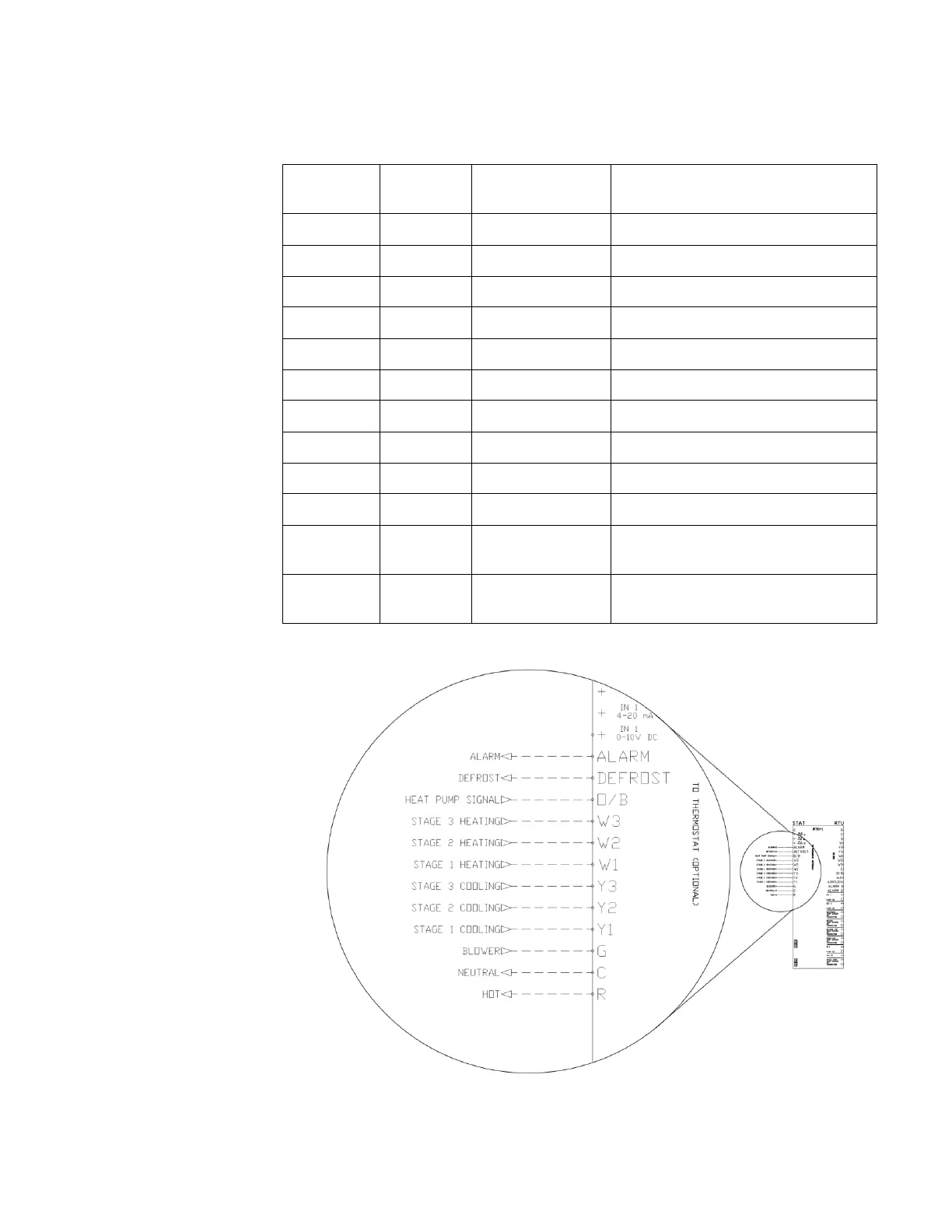
If a traditional external thermostat will be used to control the RTU, follow these instructions.
The thermostat that is being
used to control the RTU will
need to be wired to the
RTULink. Table 2 details
the “THERMOSTAT” side
terminals on the RTULink
and the corresponding
terminal definitions.
Figure 6 shows the wiring
diagram of the thermostat to
RTULink control wiring.
Figure 7 shows a detail of a
space mounted thermostat
wired to an RTULink. Not
all terminals will be wired,
view RTU and thermostat
documentation to determine
which of the terminals are
relevant to the application.
In a retrofit application, the
thermostat may already be
wired to the RTU. In this
case, there will likely be a
terminal strip in the controls
cabinet of the RTU with the
wiring from the thermostat
landed on one side and the
wiring to the RTU landed on
the other. You will need to
individually disconnect the
incoming thermostat wire and
connect it on the
“THERMOSTAT” side of the
RTULink. Do not
disconnect all of the wires
at once, disconnect wires
one at a time so it is easier to
keep track of the wiring.
When certain additional
features are present
(Occupied/Unoccupied), it is
possible for one or more of
these terminals to be
repurposed for a different
use. The remaining
subsections detail all
additional features and the
corresponding wiring
diagrams.