13
Modbus Communication Wiring
Each RTULink will need to have a path of communication to the communication module (PN: COMM01 located in the
hood panel) via a CAT5 cable. The communication module is typically located in a kitchen ventilation hood control panel,
however it is not limited to that specific location. In most cases, wiring a daisy chain configuration will require the least
amount of wire. See APPENDIX A for typical network layouts in order to determine the best configuration for the
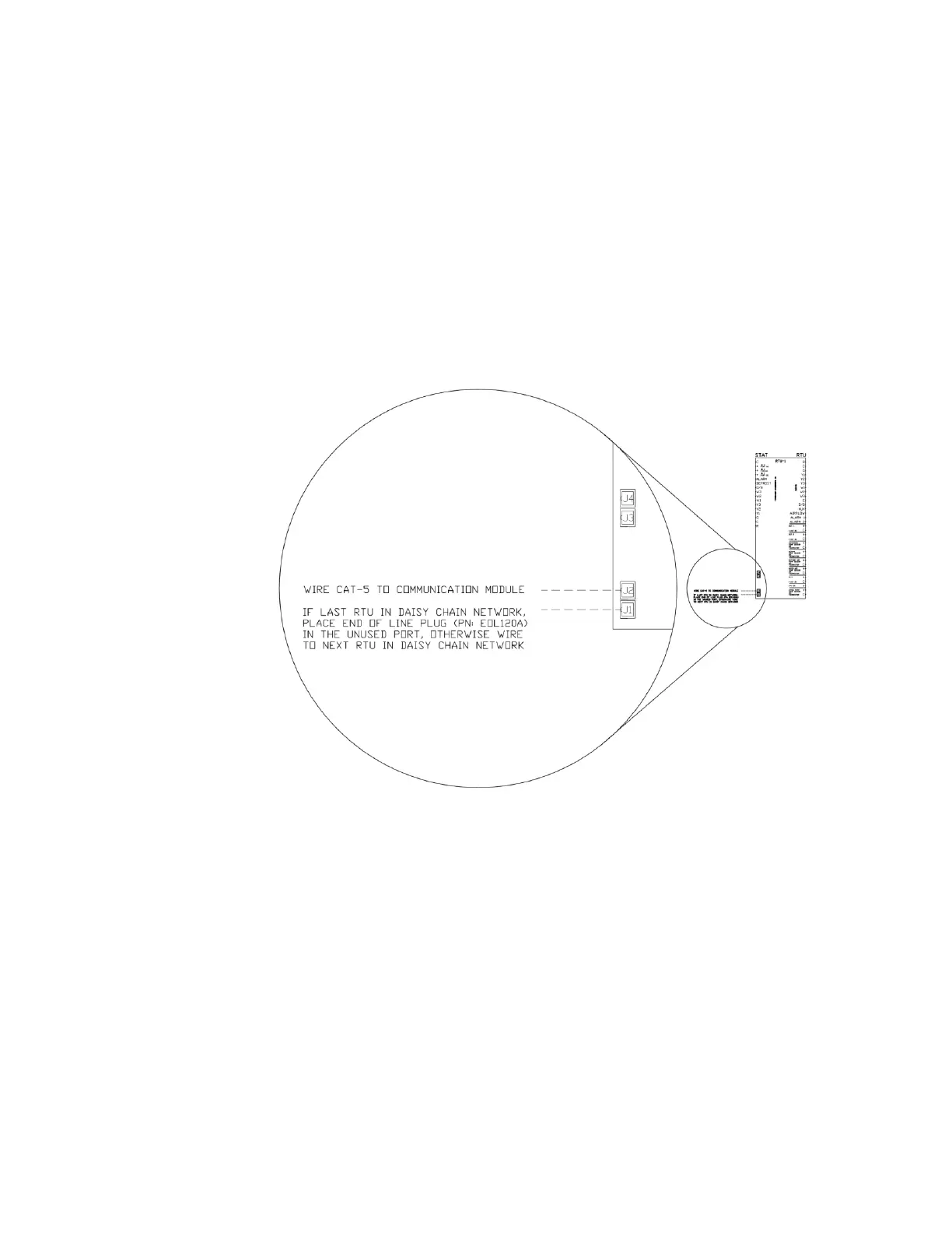
application. Use the J1 and J2 RJ45 ports to connect the RTULinks together using the CAT5 cable. If an RTULink is the
last in a line, it will only have one CAT5 cable connected to it and will require an end of line resistor (PN: EOL120A) in its
unused port (J1 or J2). Figure 11 shows a wiring detail for the Modbus communication network.
All CAT5 cables should be run without RJ45 connectors, and a crimp tool should be used to add connectors once wire
routing is complete. Each RJ45 connector wire should be wired in a T-568-B straight-through configuration. See
APPENDIX B if you are unfamiliar with how to make a straight-through CAT5 cable using RJ45 connectors and a crimp
tool. Once complete, a CAT5 tester should be used to test each length of wire.