19
Current Transducer
If current transducer(s) are called for in the specifications, follow the instructions in this section.
A current transducer (CT) will be
installed in the RTU control
panel with mounting screws or
on a piece of din rail. Energy
consumption will be measured
by routing the line wiring
through the hole in the CT. For
an RTU application, the CTs
can measure condenser power
consumption, heating element
power consumption (if electric),
or total RTU power
consumption. These lines can
usually be accessed inside of
the RTU. Refer to RTU
manufacturer documentation for
detailed wiring schematics.
Only one wire can be inserted
through each CT for measurement.
Set the current transducer jumper to monitor the closest amperage that is equal to or higher than the maximum expected
current of the circuit that will be monitored (do not account for inrush current). For example, a condenser with a maximum
amperage rating of 80 amps will have a current transducer jumper installed to monitor 100 amps (100 amp is the lowest
setting that exceeds 80 amp). Connect the positive (+) and negative (-) terminals of the current transducer to the positive
(+) and negative (-) terminals of a 0-10VDC input on the RTULink. PN: A/CTV-50 is used to measure components in the
range of 10, 20, and 50 amps. PN: A/CTV-250 is used to monitor components in the range of 100, 200, and 250 amps.
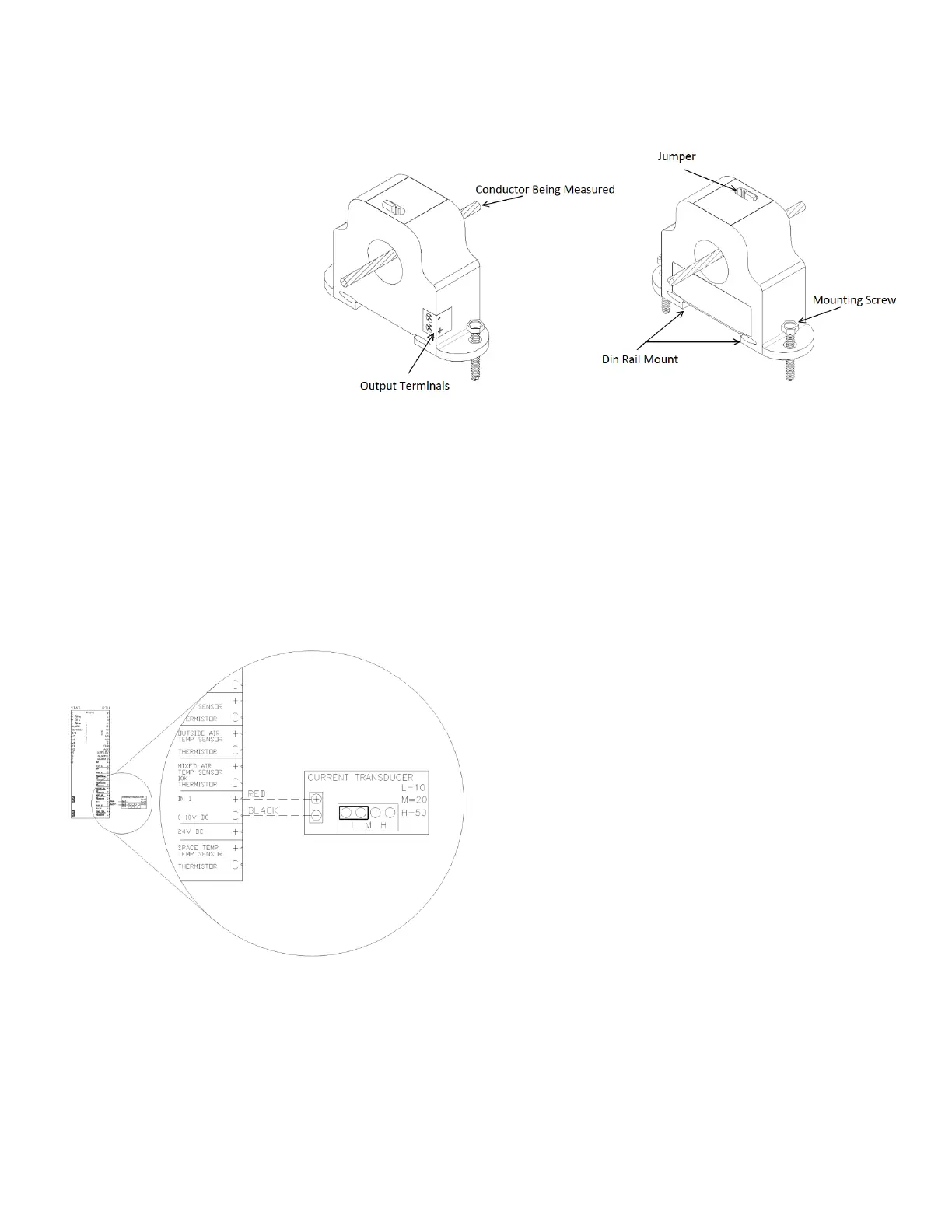
Figure 21 shows a detail and terminology of a current transducer. For specialized applications out of these ranges
contact support.
Figure 22 shows a wiring diagram of a current
transducer that is wired to Input 1 on the “RTU” side of
the board and whose jumper set to measure 10 Amps.
Standard 18-2 wire should be used for sensor wiring.
Once the sensor is wired to an input, enter the
configuration menu via the onboard HMI and configure
the corresponding input for “Current X”. The X will
represent the number of the current transducer that is
installed on the RTULink (if this is the second, the X will
be a 2). Next, “Current X” will need to be configured
with the corresponding Amps/V. In the above example,
the “RTU IN 1” would be configured for “Current 1”
(since this is the first and only current transducer wired
to the RTULink) and “Current 1” would then be
configured for 1 Amps/V.