21
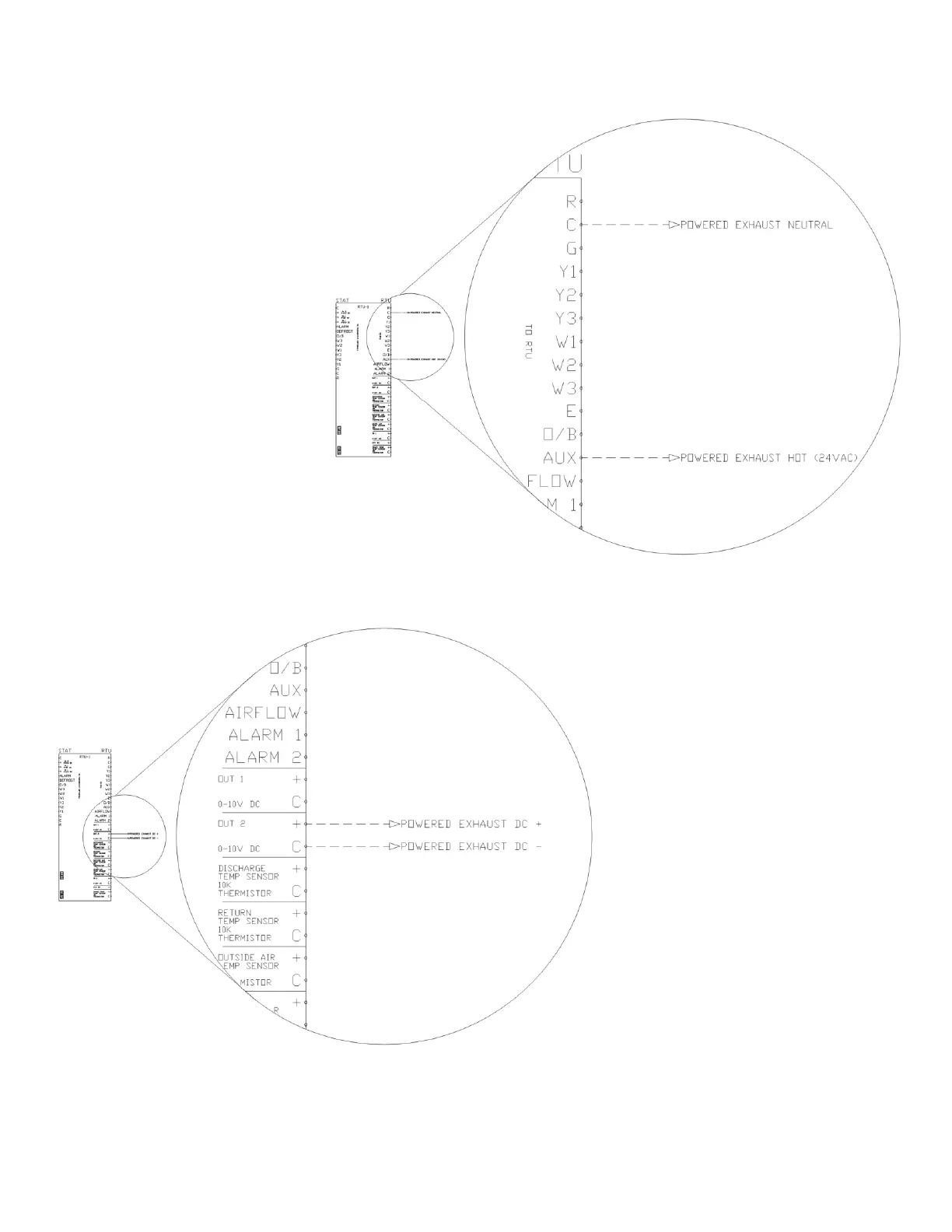
Powered Exhaust Coil Signal ON/OFF (24VAC)
If the RTULink will be using 24VAC
as the control signal for a powered
exhaust, it must be configured to
accommodate this feature. View
the FUNCTIONALITY section of this
manual to determine how to enable
a powered exhaust output and how
to change the settings that are
associated with it. If configured, the
24VAC powered exhaust signal will
use the AUX and C terminals on the
“RTU” side of the RTULink as HOT
and NEUTRAL respectively. Figure
24 is a wiring schematic for a
powered exhaust connected to AUX
and C terminals. Standard 18-2
wire should be used for output
wiring.
Note: This is a low voltage, low
amperage powered exhaust coil
signal that does not provide
power to the powered exhaust, it
only signals an ON/OFF state.
Powered Exhaust (0-10VDC)
If the RTULink will be using a 0-10VDC
as the control signal for a powered
exhaust, it must be configured to
accommodate this feature. Determine
which 0-10VDC output on the “RTU”
side of the RTULink will be used to
control the powered exhaust. Figure
25 is a wiring schematic for a powered
exhaust connected to Output #2. View
the FUNCTIONALITY section of this
manual to determine how to enable a
powered exhaust 0-10VDC output and
how to change the settings that are
associated with it. Standard 18-2 wire
should be used for output wiring.
Note: This is a low voltage, low
amperage control signal that does
not provide power to the powered
exhaust but signals a variable speed