7
INSTALLATION OF HARDWARE COMPONENTS
It is imperative that these components are installed and operated with the designed specifications and in accordance with
the procedures outlined in this manual. If there are any questions about any items, please call the service department at
1-866-784-6900 for technical support.
RTULink
Open the controls cabinet of the RTU that is being equipped
with an RTULink. Locate a spot in the controls cabinet that
will accommodate the footprint of the RTULink, leaving a
few inches on each side for wiring. Do not alter RTU factory
wiring configuration. Contact support before moving or
rerouting existing RTU wiring. Secure the board with four of
the provided self-tapping screws. Become familiar with the
terminal labeling on the RTULink.
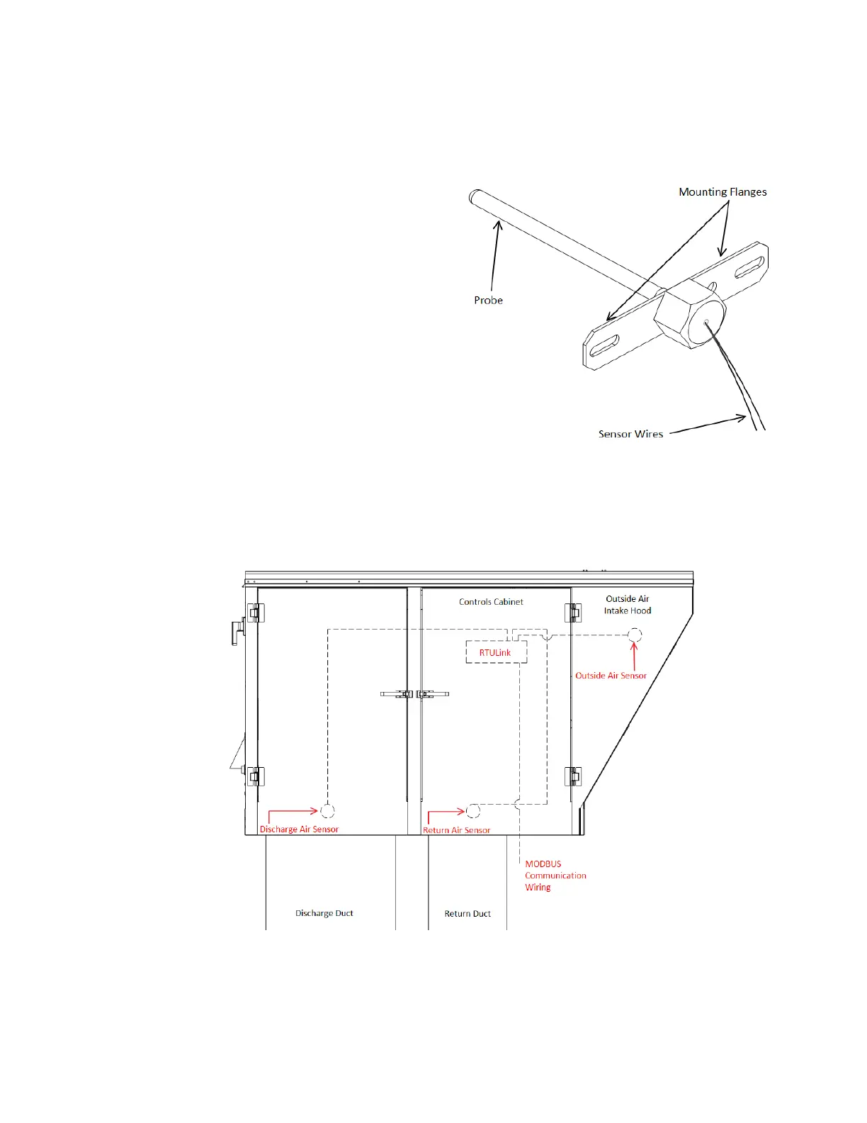
RTULink Control Kit Thermistors
Figure 2 shows a detail of one of the probe thermistors that
is included in the RTULink Control Kit. Each probe
thermistor will be wired to the RTULink. Sensor wiring and
mounting locations internal to the RTU are shown with
dashed lines in Figure 3. A thermistor wiring diagram can
be seen in Figure 4. Sensor descriptions and mounting
instructions can be found in the subsections that follow.
Note: For split system units, mount the return and discharge
sensors directly in the ductwork at a location that will not be
impacted by external factors.