18 docs.carbide3d.com support@carbide3d.com
Open the V‑Wheels
1. Figure3‑6:
a.
b.
c.
2.
eccentric nuts CLOCKWISE until the dimple is
facing UP. Refer back to Figure3‑4.
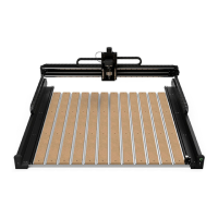
Assemble the Z‑Plus
Attach the X-Motor
1. Familiarize yourself with the features and
layout of the Z-Plus. See Figure3‑7.
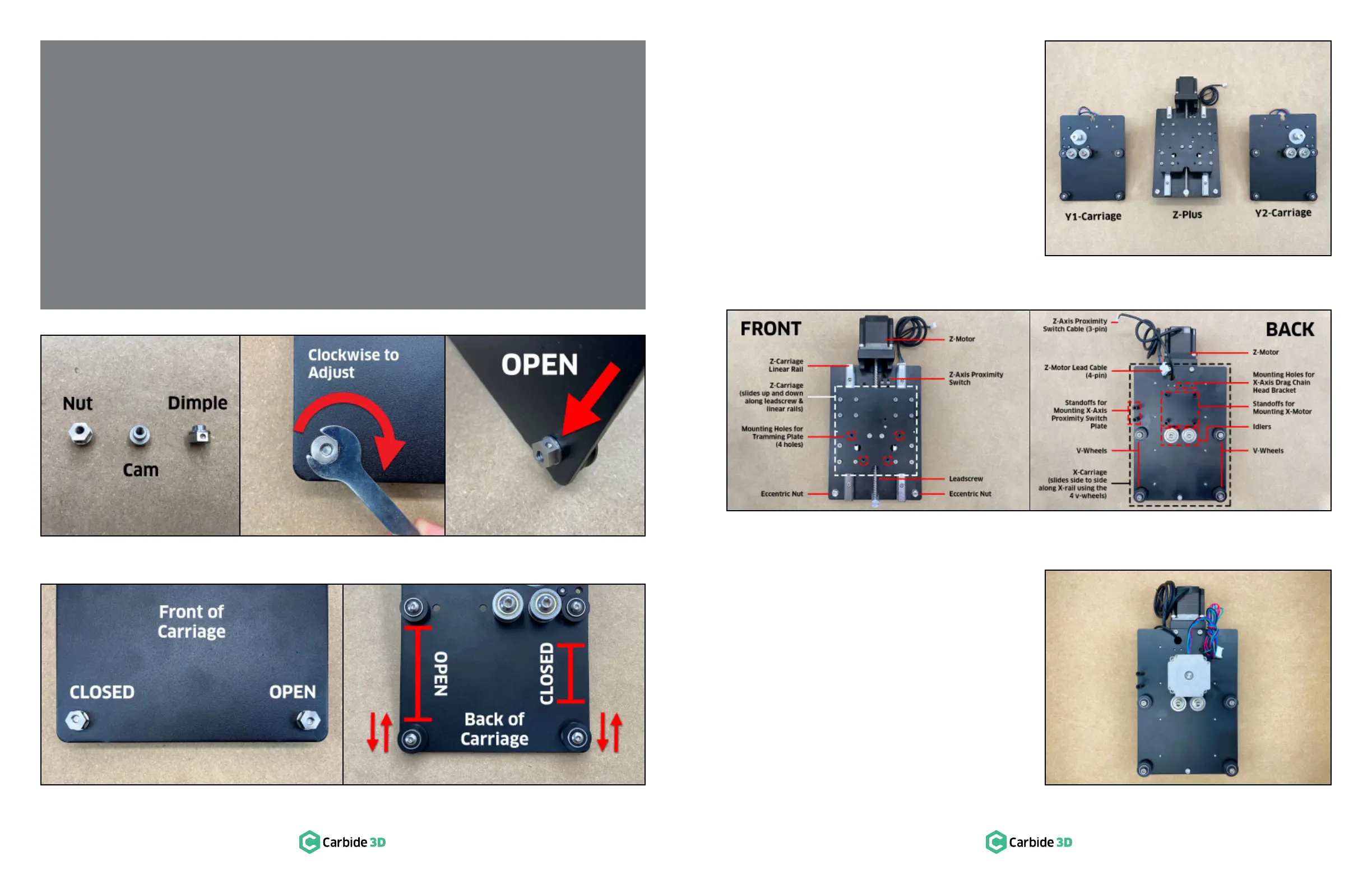
2.
30mm standoffs pointing up.
3.
spaced standoffs in the center of the Z-Plus,
with the X-motor lead cables extending up
toward the Z-motor. See Figure3‑8.
4. ×10mm
socket head cap screws to secure the X-motor
to the Z-Plus.
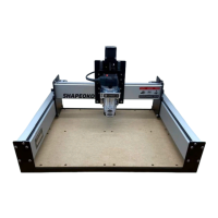
ECCENTRIC NUTS AND V-WHEELS EXPLAINED
Eccentric nuts and V-wheels are what we use to adjust the gantry at the intersect between the carriage V-wheels and the
V-rails. A loose connection here is referred to as carriage slop. To eliminate slop, a very small amount of tension is added
between the wheels and rail. Too much tension and the wheels will deform, causing bumpy and constrained motion. Not
enough tension, and the carriages will wobble. When tension is just right, the carriages glide smoothly and without slop for
the highest-quality cuts.
Our HD eccentric nuts, in combination with the attached V-wheel, operate as a cam, converting the rotational motion of
turning the nut, into linear motion at the V-wheel. A dimple on one the side of the nut indicates the furthest point to center
of the offset threads. When the dimple is facing UP, the distance between the top and bottom wheel is at its greatest and
the V-wheels are OPEN. When the dimple is facing DOWN, the opposite is true, and they are CLOSED. See Figures 3‑4 and
3‑5.
When adding tension to a loose V-wheel, turn the eccentrics clockwise. Turning counter-clockwise will loosen the bolted
connection between nut and wheel. If this happens, re-tighten with a 10mm wrench and a 3mm or 4mm hex key.
Not much tension is needed for the carriages to be secure. The wheels should only be snug against the rail. Reach under
and spin the V-wheel with your nger. If it rotates freely, turn the eccentric nut clockwise until you feel some friction against
the rail and the carriage is free from slop.
Figure3-5
Figure3-4
Figure3-6
Figure3-8
Figure3-7
 Loading...