20 docs.carbide3d.com support@carbide3d.com 21
Identify the Front of the
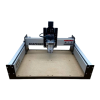
Tramming Plate
a feature of the Z-Plus made possible by the
tramming plate. Tramming before each new project
sets the router mount perfectly parallel to the
Three of the four M5 mounting holes on the
tramming plate are enlarged by 0.75mm. The one
point around which the plate can “wiggle” by +/-
be in the UPPER-LEFT corner when the plate is mounted to the Z-Plus. This is considered the FRONT of the
tramming plate.
1. Position the tramming plate with the short legs extending up in a “U” shape. See Figure3‑9.
2. Inspect the top two screw holes to determine which of the two is the smaller.
3. Position the tramming plate with the smaller hole at TOP-LEFT. This is the FRONT of the plate.
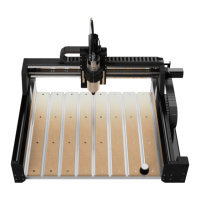
Attach the Router Mount to the Tramming Plate
The router mount attaches to the FRONTUP.
1.
back of the router mount AND×
2.
M5×
secure the router mount to the FRONT of
the tramming plate and fully tighten. See
Figure3‑11.
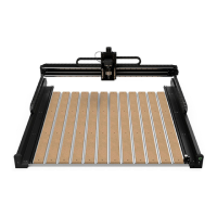
Attach the Tramming Plate to the
Z-Plus
1. Set the tramming plate onto the front of the
2. ×8mm
socket head cap screws to secure the plate to
the Z-Plus. See Figure3‑12.
3.
mount adapter ring into the router mount. If
and can set it aside.
4. Insert the two M5×55mm socket head cap
screws into the front of the router mount and
5. Grasp the sides of the Z-Plus with both hands
and lower the Z-carriage with your thumbs
until it stops at the bottom. See Figure3‑13.
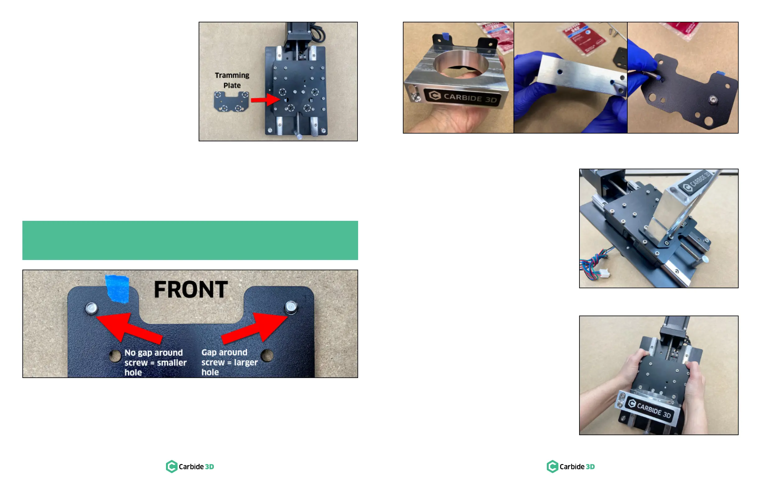
PRO TIP: Insert the tramming plate hardware, two (2) M5×8mm screws, from the back and examine
each screw hole for a gap. The larger hole will leave a gap around the screw, the smaller hole will
not. Mark the smaller, standard-sized M5 screw hole with a piece of tape. See Figure3‑10.
Figure3-10
Figure3-9
Figure3-12
Figure3-11
Figure3-13
 Loading...