8400-0181-OM Rev C 185 and 185B Installation & Technical
9
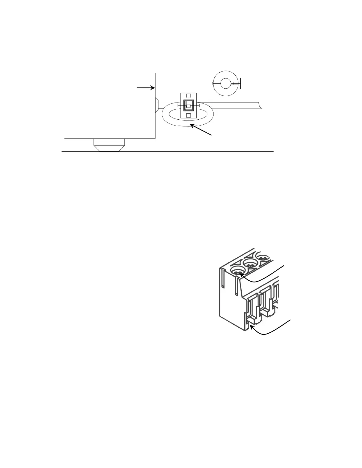
Scale End Load Cell Cable Ferrite Core
The included round snap-on ferrite core must be attached to the load cell cable near the scale
end of the cable. The ferrite core must be attached to the cable with one turn as shown in
Figure No. 7. Wrap the load cell cable around one side of the core, and then snap it closed.
Make sure sufficient pressure is applied to completely latch the core to the cable.
Figure No. 7
Serial I/O Cable Installation
The Model 185 and 185B may be connected to a printer to record weight and associated data
or it may be connected to a remote display or to a computer for transmission of weight data.
The weight data, may be transmitted on demand (pressing the PRINT key or on receipt of a
command from the computer). Refer to the Setup, SIO Serial I/O section of this manual.
1. Remove the four (4) Phillips screws securing the back panel to main housing, and then
loosen the right gland connector for the serial cable. Refer to Figure No. 2 for illustration of
connector layout.
2. Slip the serial cable through the gland connector and into the enclosure.
3. Remove 2" (50mm) of the outer insulation jacket then
remove 1/4" (6mm) of insulation from each of the
wires (refer to Figure No. 4).
4. Connect each of the wires to the Serial Data terminal
block (P6) referring to Figure No. 9 for terminal block
locations.
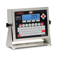
5. To terminate, make sure the terminal screw is
backed off enough, insert the wire into the opening,
then tighten the screw. Repeat the procedure until all
of the wires are in place.
Insert
Wire
Tighten
Screw
Figure No. 8
Back of Scale
Wrap one turn of load cell
cable around ferrite core.
Round Snap-on
Ferrite Core
Front View
Round Snap-on
Ferrite Core
Load Cell Cable