9
ENG
clima +030220641 - rel. 1.0 - 07.12.2007
2. INSTALLATION
Below is a description of the recommended operations for correct
installation.
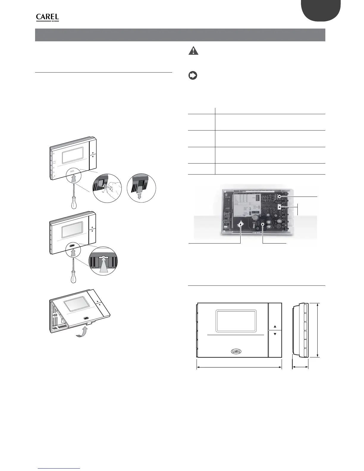
2.1 Assembly
Open the product by detaching the front part from the mounting base,
as shown in Fig. 2.a:
Using a screwdriver, remove the screw holding the tab in the •
opening.
Once having removed the screw, slide the plastic tab as shown in the •
gure so as to remove it from the instrument and be able to lever the
catch.
To open the instrument, press the tab on the front by inserting a at-•
head screwdriver into the slit in the middle on the bottom of the case
and at the same time ip the front panel upwards.
clock
set
mode
fan
hold
resume
aria
clock
set
mode
fan
hold
resume
aria
Mode
Fig. 2.a
Once having completely removed the cover of the instrument, the two •
parts remain connected by a at cable that can be disconnected from
the front panel.
Fasten the bottom of the clima to the wall using the screws contained •
in the packaging. For drilling, use the template on the rear of the
packaging
To connect the wires to the terminal block, remove the terminal covers •
by squeezing the two ns.
Make the required connections according to the model chosen,
•
running the connection cables through the hole in the middle of the
bottom shell and connecting them to the terminal block, observing the
indications on the label. Separate the connection and control cables
from the relay cables. The wiring diagrams are shown in paragraph
2.3.
Important: Make sure all the power supply lines have been
connected, both low voltage (24 Vac/dc) and, where necessary, high
voltage for the relays (230 V), before reconnecting the front part of the
instrument using Front-Rear at cable.
Note: For the purposes of electrical safety (EN60730-1), once the
controller has been installed, tighten the plastic tab in the housing for
opening the instrument.
Accessories and dipswitches (Fig. 2.b)
Connector Function
J1 - Supervisor serial connection using code IROPZ48500.
- Key connector for copying the parameters. The serial
connection, if used, must be momentarily disconnected..
J2 Used to connect the remote temperature and humidity
sensor ADCF006500. Also use the centre screw for the lug
connected to the cable shield.
FLAT
Front-rear
The at front/rear connection cable must be reconnected
in the position de ned by the plastic part to ensure correct
polarity
Dipswitches For con guring operation and cooling/heating,
humidi cation/dehumidi cation modes
Tab. 2.a
J2 = sonda esterna T+H - ADCF006500
J1 per opzione
seriale o chiave
di programmazione
FLAT Front-Rear
Dip-switches
Fig. 2.b
2.2 Dimensions
For installation, see the drilling template included in the packaging.
clima
135
36
86
Fig. 2.c