[a]
[b] [c]
[13]
9
108
6
543
9
10
6
5
9
10
6
5
F=315mA
[10]
[11]
[12]
DIN
kWhkW
1
2
3
45
67
89
10
11
12 13
14 15
16 17
18
S1 S2
CT3
P1 P2
S1 S2
CT2
P1 P2
N
N
L1
L1
L2
L3
L2 L3
GND
not used
not used
ending
dig. output
dig. output
RS485
–+
Load
S1 S2
CT1
P1 P2
P1
LOAD
Current Transformer
P2
S1
S2
17
18
G
VDC/AC
18
16
15
17
18
16
15
17
ITA
29
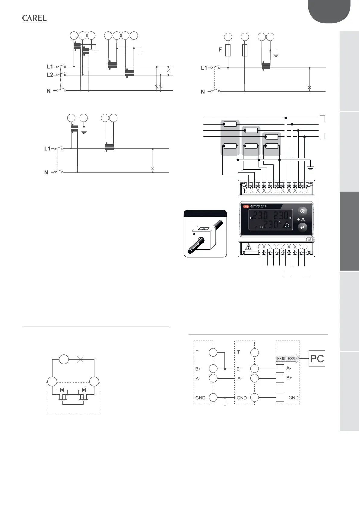
"Carel emeter" +0300044IE rel. 1.5 - 10.11.2017
emeter3 SE
4.3 Schema di collegamento porta seriale
RS485
NOTA: ulteriori strumenti dotati di porta seriale sono collegati come
nella figura qui sopra riportata. La terminazione della rete deve essere
eseguita solo sull’ultimo strumento mediante un ponticcello tra (B+)
e (T).
4.2 Schema di collegamento uscita statica
(*) opzionale